background image

6

Calibration

Initialize In/Out

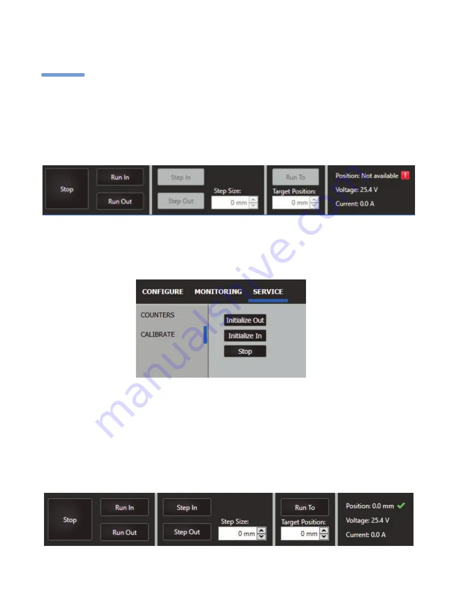
To begin calibration, simply click on the “Service” tab at the top of the window, then select “Calibration” on the 
left menu. 

Once this process is complete, you’ll find that the position is now available. 

The IC platform uses hall effect sensors to determine the actuator’s exact position along its stroke length. If once 
connected, the actuator’s position status is displayed as “Not available”, then the actuator must first be calibrated 
to use the full control functionality within the software. A calibration is required each time new parameters have 
been applied for the actuator’s behavior. Calibration happens automatically whenever the actuator hits a limit 
switch, so it is not necessary to be connected to BUSLINK for this to occur. 

From here, determine where your actuator’s current position is. If the actuator is fully extended, then select 
“Initialize In” to run the actuator to the inwards limit switch. If the actuator is fully retracted, then select “Initialize 
Out” to run the actuator to the outwards limit switch. If the actuator is somewhere in between fully extended and 
fully retracted, selecting either “Initialize In” or “Initialize Out” will successfully calibrate the system. 

Summary of Contents for BusLink LA14

Page 1: ...LINAK COM TECHLINE BusLink User Guide...

Page 2: ...tware 5 11 Controls 5 7 Configure 5 Calibration 6 Virtual and Current Limit 7 Speed 8 Soft Stop Soft Sart 8 Feedback Types 9 11 PWM 9 Single Hall 9 Current Feedback 10 Voltage Feedback 10 Monitoring 1...

Page 3: ...1 Start by downloading the free BusLink software here WWW LINAK COM SEGMENTS TECHLINE TECH TRENDS IC AND BUS ACTUATORS LA14 LA25 IC blue interface 0147999 LA33 LA36 LA37 IC blue interface 0367999 LA36...

Page 4: ...that this is done carefully in order to protect the plugs and pins Please make sure that the plug is in the right place and fully pressed in before mounting the cable lid Cable connection and plug in...

Page 5: ...trary specified position The actuator s current status is shown on the right These values are actively recorded in a graph that will be explained later in this user guide Once connected you will be ab...

Page 6: ...in the software A calibration is required each time new parameters have been applied for the actuator s behavior Calibration happens automatically whenever the actuator hits a limit switch so it is no...

Page 7: ...ions The maximum current will not exceed the maximum factory settings Note If the actuator operating temperature reaches O0 C 320 F the current limits are removed Virtual Limit A virtual end stop can...

Page 8: ...ft stop you select a time frame for the actuator to slow down to zero after the stop signal is applied The time can be set between 0 hard stop and 30 sec with the exception of 0 1 299 ms The reason fo...

Page 9: ...iable parameters The pulse width modulation PWM type is configurable with three parameters PWM Feedback In sets the percentage of the pulse for the IN End of Stroke EOS postion The PWM Feedback Out se...

Page 10: ...ange The minimum setting is the IN EOS or virtuel limit in position and the maximum is the OUT EOS or virtuel limit out The position of the actuator can be correlated to a voltage output as well The a...

Page 11: ...zooming and a snapshot as an image The graph auto scales when taking a snapshot You can save a snapshot as an image or as a dataset This snapshot shows the actuator moving from the OUT EOS position t...

Page 12: ...d Non critical When you select a number of actuators for your system the operation is considered Critical When connected the actuators are looking for the correct number of online actuators If one bec...

Page 13: ...reland Phone 44 0 121 544 2211 Fax 44 0 121 544 2552 44 0 796 855 1606 UK Mobile 35 387 634 6554 Republic Of Ireland Mobile E mail sales linak co uk www linak co uk Italy LINAK ITALIA S r l Phone 39 0...

Reviews: