background image

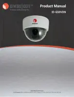
VANDAL RESISTANT COLOR DOME CAMERA

Model No.

Power Input Voltage

System

Sync. Mode

Pick Up Element

Effective Pixels

Chip Size

Scanning System

Resolution

Minimum Illumination

S/N Ratio

Auto Gain Control

Aperture Correction

Power Consumption

Shutter

Back Light Compensation

Video Output

Gamma Characteristic

Lens

Operating Temperature

Weight

Dimension

DC12V ( 10%)

NTSC or PAL

Internal

1/3" Super HAD CCD Sensor

5.59mm (H) x 4.68mm (V)

2

1 Interlace

540TV Lines

0.5Lux (F1.8)

More Than 50dB (AGC OFF)

36dB Variable Gain

Horizontal , Vertical

2.2W

1/60(1/50)S ~ 1/100,000S(Auto)

Auto

CVBS 1.0Vp-p , 75ohm

=0.45

-10

~ +50

(14

~ 122

)

Base :

136 x 55mm , Dome :

91.8

768(H) x 494(V) [NTSC]

752(H) x 582(V) [PAL]

15.734KHz / 59.94Hz [NTSC]
15.625KHz / 50Hz [PAL]

Horizontal & Vertical
Sync. Frequency

Focal Length

Iris

Angle of view

3.6mm

6.0mm

F2.0

F1.8

Option lens

8.0mm lens.

Design and specifications are subject to change without notice.

White Balance

ATW

1200g

H

V

D

3.6mm

6.0mm

F2.0

F1.8

54.5

33.1

73

44.5

92

56

54.5

33.1

73

44.5

92

56

510(H) x 492(V) [NTSC]

500(H) x 582(V) [PAL]

380TV Lines

0.2Lux (F1.8)

IP Rating

IP68

PIH-2242

3.6 PIH-2242

6

PIH-2222

3.6 PIH-2222

6

SPECIFICATIONS

Vandal Proof

Withstand a blow from a 10 lbs sledgehammer

Summary of Contents for PIH-2222

Page 1: ...INSTRUCTION MANUAL VANDAL RESISTANT CAMERA PIH 2222 2226 2242 2246 E VANDAL RESISTANT VARI FOCAL CAMERA PIH 2322X 2326X 2342X 2346X...

Page 2: ...flash with arrowhead symbol within an equilateral triangle is intended to alert the user to the presence of uninsulated dangerous voltage within the product s enclosure that may be of sufficient magn...

Page 3: ...0 99 5 HOLE PLUG SIDE HOLE INSTALLATION 2 Put the provided screws M3 0 x 25 wooden screw through the holes marked as a and fix the base in the desired area FIG 1 1 Please use the enclosed screw drive...

Page 4: ...FIG 5 ATTENTION Adjust this VR with care so as not to cause damage to the unit 7 Put on the dome cover first Then tighten the tamper proof screws FIG 7 4 The direction of the lens is adjustable throu...

Page 5: ...FIG 1 a a a VIDEO OUT VIDEO GND POWER INPUT FIG 3 FIG 2...

Page 6: ...FIG 4 PIH 222 224 BRACKET TILT FIG 5 PIH 232 X 234 X TILT PAN BRACKET ZOOM ADJUSTMENT FOCUS ADJUSTMENT IRIS LEVER VR SCREW DRIVER AZIMUTH PAN AZIMUTH...

Page 7: ...FIG 6 FIG 7...

Page 8: ...om hole and connect them to the terminal block on the PCB accordingly Please refer to INSTALLATION Step3 for water resistant installation 3 Fix the cable with cable clamp 1 Untighten the hole plug on...

Page 9: ...B Variable Gain Horizontal Vertical 2 2W 1 60 1 50 S 1 100 000S Auto Auto CVBS 1 0Vp p 75ohm 0 45 10 50 14 122 Base 136 x 55mm Dome 91 8 768 H x 494 V NTSC 752 H x 582 V PAL 15 734KHz 59 94Hz NTSC 15...

Page 10: ...AGC OFF 36dB Variable Gain Horizontal Vertical 2 5W DC12V 2 0W AC24V 1 60 1 50 S 1 100 000S Auto Auto CVBS 1 0Vp p 75ohm 0 45 10 50 14 122 Base 136 x 55mm Dome 91 8 768 H x 494 V NTSC 752 H x 582 V P...

Page 11: ...ohm 0 45 10 50 14 122 Base 136 x 55mm Dome 91 8 768 H x 494 V NTSC 752 H x 582 V PAL 15 734KHz 59 94Hz NTSC 15 625KHz 50Hz PAL Horizontal Vertical Sync Frequency Focal Length Iris Angle of view Design...

Page 12: ...MERIT LILIN ENT CO LTD http www meritlilin com 66 222CSE...

Reviews: