background image

Technical Description &

 Configuration Guide


RSSI

 Port


LigoWave 

Page 86


RSSI (Received Signal Strength Indicator) port is used to adjust the alignment of antenna for best 
performance (for both rough and fine adjustment); this can be done using digital multimeter which is 
connected to the RSSI port. The output of the RSSI port is DC voltage and varies depending on 
received signal level.  

The following chart and table shows typical relationship of the received signal level (Rx level) displayed 
by LigoPTP 24 vs. RSSI port output voltage (RSSI 

– Received Signal Strength Indicator). The RSSI 

port is located on FODU. The evaluated Rx level has the error +/-2 dBm.  


RSSI Port 

Summary of Contents for LigoPTP 24 Series

Page 1: ...LigoPTP 24 Technical Description Configuration Guide Revision 1 0 December 9 2009 Copyright 2009 LigoWave www ligowave com...

Page 2: ...out prior notice While the information in this manual has been compiled with great care it may not be deemed an assurance of product characteristics LigoWave shall be liable only to the degree specifi...

Page 3: ...or 14 Ethernet Management Connection Configuration 15 Power over Ethernet Injection 18 Termination Panel for 4 E1 and with Power Injector LigoPTP TP4 19 Connection with Web Interface 19 Interface Desc...

Page 4: ...rm and Alarm Threshold Configuration 62 Alarm Management Commands 64 Performance Management 65 Performance Management Data Collection 65 Performance Values 66 Threshold Seconds TS 66 Tide Mark TM 66 P...

Page 5: ...t is possible to configure the radio to any of 7 MHz 14 MHz and 28 MHz channels as well as to any of QPSK 16APSK and 32APSK modulations thus providing various capacities to suit particular needs LigoW...

Page 6: ...et traffic supports QoS and 4 priority queues essential for ACM use User and NMS traffic could be treated as a single data stream or separated by tagging with different VLAN tags 4 ports of balanced E...

Page 7: ...d at BER 10 6 28MHz 32APSK 100Mbps 77 dBm System Gain with guaranteed max Tx power and Rx sensitivity is 93 dB LigoPTP 24 provided the capability to replace typical 34Mbps PDH radio to 108Mbps system...

Page 8: ...se perfect for overlaying GSM network with 3G WiMax and LTE Long Term Evolution services Suitable for transition from TDM to Ethernet based networks LigoPTP 24 FODU supports SNMP protocol for NMS Low...

Page 9: ...U Suitable for any 100Mbps Ethernet network topology star ring mesh network Full Outdoor solution with Power over Ethernet Plus is efficient for All Outdoor Base station connectivity Last Mile Access...

Page 10: ...ing temperature range 33o to 55oC Mechanical Data Dimensions HxWxD in weight lb without antenna 11 2x11 2x3 1 7 7 Max power consumption 15 20 W Management Options TCP IP WEB SNMP Telnet local and remo...

Page 11: ...m at 49 2 Mbps 88 dBm at 73 6 Mbps QPSK wide 94 dBm at 13 8 Mbps 89 dBm at 30 4 Mbps 86 dBm at 61 8 Mbps 84 dBm at 92 6 Mbps 16APSK 89 dBm at 23 6 Mbps 86 dBm at 48 6 Mbps 84 dBm at 98 6 Mbps 81 dBm a...

Page 12: ...enuation which must not exceed 6 dB 10 100Base T Cat 5e UTP or better cable is required for power supply management of device and data traffic LigoPTP 24 FODU can be used with any LigoWave additionall...

Page 13: ...side L H the FODU operates Letters A B C or D indicate specific subband Unit Serial Number 3163901 00001 the serial number uniquely identifies the FODU Figure 5 Labels of the LigoPTP 24 FODU Low and H...

Page 14: ...h button in Web GUI Configuration System configuration window or using command prompt command system reset Restarts CPU of the management controller Resets all management counters Resetting with comma...

Page 15: ...r into the socket by pushing the cable and at the same time seal and fix the cable using cable sealing screw 6 Assembled cable Please fix the cable to the mast as close as possible to FODU Do not bend...

Page 16: ...ows operational system go to Start Settings Network connections or Start Settings Control panel Network connections Step 2 Find Local Area Connection click right mouse button on it and choose Properti...

Page 17: ...e Configuration and Management LigoWave Page 17 Step 4 In the dialog box enter the following values so that your PC is in the same subnet as default LigoPTP 24 addresses Now you are ready to connect t...

Page 18: ...well as its application scheme Figure 8 Passive Power over Ethernet Injector P N I0ATPI01 Figure 9 Power over Ethernet Passive Injector Application This passive injector features shielded RJ 45 jacks...

Page 19: ...of the Power over Ethernet not 802 3af technology which utilizes spare leads on the cable to the LigoPTP 24 FODU from the FODU port connector and provides appropriate voltage 48V and power 25W see the...

Page 20: ...to the real page If the IP address is not valid you will not get configuration interface but if your browser is not accepted not recommended or there are problems with the version you will see the te...

Page 21: ...and remote devices this section is available while browsing other pages The main panel where the new pages selected from the menu panel are loaded for display Also special marks are used Entries high...

Page 22: ...to previous configuration in case of management connectivity loss 5 Write to config file button which generates cfg write CLI command which saves changed configuration 6 Configuration parameter name 7...

Page 23: ...with the explanation text Figure 15 Web Interface IP Configuration Page with Numbering Initial Configuration with Web GUI Your connected laptop should be in the same subnet with manageable LigoPTP 24...

Page 24: ...ault IP addresses Currently supported browsers you can use are Internet Explorer Mozilla Firefox Opera and Safari Figure 16 Supported Browsers When you are connected to the LigoPTP 24 FODU you will se...

Page 25: ...nts Default password for admin account is changeme guest account is disabled by default The next time you will try to access the Web GUI management you will be asked to enter the user name guest or ad...

Page 26: ...overall link capacity Figure 20 Defining modem bandwidth modulation and the number of E1 channels The next step is radio configuration It primarily shows the radio data status and allows specifying th...

Page 27: ...lnet management are found in detailed explanation of Web GUI windows as well as in tables of additional commands To end Telnet session press Ctrl D Opening the session again the prompt will appear to...

Page 28: ...onnection options to LigoPTP 24 FODU When using modems the management terminal is connected with the LigoPTP 24 FODU remotely through a telephone line In this case the modem connected with the LigoPTP...

Page 29: ...29 Step 4 Choose port COM1 or COM2 Step 5 Set port settings bits per second 19200 data bits 8 parity none stop bits 1 data flow control none Step 6 Press OK Step 7 Press Enter Password is disabled by...

Page 30: ...hen you are ready to connect to Telnet interface please follow these steps Step 1 Go to Start Run Step 2 Type in telnet ip_addr where ip_addr is IP address of the LigoPTP 24 FODU you want to connect t...

Page 31: ...set above mentioned parameters you must know what frequency and bandwidth you may use and at what power you may transmit Modulation with the command modem modulation QPSK 16APSK 32APSK wide ACM Number...

Page 32: ...ection to LigoPTP 24 management port was lost 2 Shows the firmware version this LigoPTP 24 FODU is currently using 3 Logout button allows ending the current Web GUI management session and logging in a...

Page 33: ...from modem Modem status indicates the acquire status of the modem ACQUIRE_IN_PROGRESS will appear during start up when modem acquires required parameters but in normal operation mode ACQUIRE_LOCKED w...

Page 34: ...the received constellation Radial MSE peak value threshold is dependent on modulation used and LDPC code rate If the Radial MSE value trespasses following thresholds BER at the output of LDPC decoder...

Page 35: ...n type and LigoPTP 24 model Maximal and minimal Tx power values are shown in the brackets command line radio txpower power dBm Tx frequency 22014000 22582000 KHz allows you to enter preferable transmi...

Page 36: ...rection step 1 5 dBm Tx power correction displays the amount of transmitter power in decibels ATPC has currently corrected command line atpc status Tx power correction limit 19 1 dB allows defining th...

Page 37: ...th ACM to control the transmitted power in any given ACM profile Different algorithms can be implemented to achieve maximal spectral efficiency or minimal transmitted power using both features in comb...

Page 38: ...sponding section only for the local side LigoPTP 24 FODU If Rollback on is selected configuration will be reverted in case of erroneous configuration changes applied Pressing Execute for both applies...

Page 39: ...in the link performance the new ACM profile will include lower modulation decreasing the link bitrate The ACM switching rate is measured in dB s and is a key feature of ACM systems In general the hig...

Page 40: ...ack tests are accessible using local or remote management methods For safety purposes all loopbacks local and remote can be set on a fixed time interval only If no time interval is specified the defau...

Page 41: ...lt Tx power will be turned off max option will switch Tx power to the maximum value after restart Additional loopback commands in Telnet serial interface is provided in the table below Command Descrip...

Page 42: ...e additional user management commands in Telnet serial interface Command Description access login name password Logs on as a user specified by name and password access logout Logs current user out acc...

Page 43: ...ge command line cfg write Immediate CPU restart restarts LigoPTP 24 FODU you are connected to command line system reset Note that after restarting the LigoPTP 24 will use only those settings which are...

Page 44: ...Ethernet Management Port IP Configuration IP Address allows specifying IP address of LigoPTP 24 FODU you are currently logged in Default IP address is 192 168 205 10 or 192 168 205 11 depending on wh...

Page 45: ...e net route Network address allows specifying network address for the route changing adding command line net route add delete dest addr MASK mask gateway Network mask allows specifying network mask fo...

Page 46: ...ea change For the purpose of illustration we use B class IP network address 10 0 10 11 for the remote side LigoPTP 24 and 10 0 10 10 for the local side LigoPTP 24 while the IP address of our managemen...

Page 47: ...d line ethernet stat Explanation of customization fields Ethernet Status Represents all three ports of the LigoPTP 24 FODU switch Local Area Network LAN port Wide Area Network WAN port and Management...

Page 48: ...plied Pressing Execute configuration applies changes made to the corresponding section Write to config file writes to configuration file all the changes made on the whole page command line cfg write F...

Page 49: ...ted configuration will be reverted in case of erroneous configuration changes applied command line ethernet vlan VLAN ID Trunk Access Reset VLAN resets the whole VLAN configuration command line ethern...

Page 50: ...atus and Settings Figure 30 System without VLANs When VLANs are not used Figure 4 6 user data and management data are not separated either logically or physically When using VLANs Figure 4 7 it is nec...

Page 51: ...1 Switch 2 CPU 2 CFIP1 CFIP2 User data MM data User data MM data Port 1 Port 2 Port 3 Port 1 Port 2 Port 3 Port 3 Port 3 Port 1 Port 1 Port 2 Port 2 VLAN A B VLAN A B VLAN A B VLAN A B VLAN A VLAN B V...

Page 52: ...espectively Limitations and rules on using VLAN Supports up to 16 full range VLAN IDs If hardware VLAN table is full software responds with the error message Error VLAN table is full Only one VLAN wit...

Page 53: ...iption Configuration Guide Detailed Configuration in Web LigoWave Page 53 Examples of VLAN usage Figure 34 VLAN configuration with VLAN tag encapsulation on the ISP side Figure 35 VLAN configuration w...

Page 54: ...ort map DiffServ enables or disables DiffServ DSCP priorities for all three ports LAN WAN and Mng command line ethernet QoS DSCP enable disable port map Port based priority allows passing packets from...

Page 55: ...orts LAN WAN and Mng command line ethernet QoS DSCP enable disable port map Port based priority allows passing packets from ports LAN WAN or Mng directly to a specific priority queue By default port b...

Page 56: ...al side LigoPTP 24 FODU If Rollback on is selected configuration will be reverted in case of erroneous configuration changes applied Write to config file writes to configuration file all the changes m...

Page 57: ...being shown here Otherwise it says Ok SNMP Configuration The SNMP configuration window provides the configuration of SNMP communities host and trap addresses Explanation of customization fields SNMP...

Page 58: ...IP address to the LigoPTP 24 SNMP host table If the SNMP host connected to the LigoPTP 24 is not added to the LigoPTP 24 SNMP host table the LigoPTP 24 will not respond to the SNMP requests from that...

Page 59: ...vents and event groups Alarm ID Group ID Alarm Event name Description 1 1 System Start Software started Only rising 2 2 Invalid device license License is not valid 3 3 License expired License validity...

Page 60: ...tage out of defined range 25 18 5 0V failure Power supply voltage out of defined range 26 19 No data from RADIO No data from radio for future compatibility 27 20 Rx level alarm Rx alarm level is out o...

Page 61: ...seen in the table above or using the command alarm list in the command prompt To configure representation of alarms refer to chapter Adaptive Equalizer Figure 39 Alarm status window Alarm Log To view...

Page 62: ...igure 40 Alarm log window Alarm and Alarm Threshold Configuration The alarm configuration screen allows you to configure alarm representation You have a choice to see specific alarm groups globally in...

Page 63: ...Alarm configuration window Alarm threshold configuration screen allows you to define specific threshold levels to bound alarms to desirable values so that you are able to adapt alarm system to your in...

Page 64: ...he latest 20 log entries the log entries are numbered entry with the largest number is the latest event The log show command can be followed up with an entry number to display the latest 20 entries be...

Page 65: ...our List reserved space for every time interval is 1440 records see Figure 43 Functional architecture for data collection history and thresholding treatment Second by second the input performance even...

Page 66: ...t value assumed at the beginning of each measurement period The TM is therefore composed of two values the minimum and the maximum value Comparison between the current value and the minimum and maximu...

Page 67: ...be counted you must go to Configuration Performance log configuration and enter preferable threshold values Refer to sections Performance Management Data Collection and Performance Values for further...

Page 68: ...fields The date format is yy mm dd the time format is hh mm 6 Sets date and time fields point 6 one screen back forth 7 Shows updates the performance graph using the period settings point 5 8 Perform...

Page 69: ...he type of interference and distortion in a signal For the purpose of analyzing the received signal quality some types of corruption are evident in the constellation diagram For example 1 Gaussian noi...

Page 70: ...In wireless telecommunications using QAM modulation this filter equalizes not only a separate quadrature channel but provides a cancellation of cross interference between them In current LigoPTP 24 de...

Page 71: ...aps graph otherwise frequency response curve will appear jagged and many equalizer taps will become visible The latter case most probably will indicate to multipath issue which must be inspected with...

Page 72: ...ring start time or date respectively pm select Up_TIME Rx_LEVEL Tx_LEVEL SYS_TEMPER RADIAL_MSE LDPC_STRES ALL NOT Allows selecting the system parameters to be monitored and shown in the performance ma...

Page 73: ...or a false carrier was detected noted and reported with this the next receive statistics The false carrier is not associated with this packet False carrier is activated on the receive channel that doe...

Page 74: ...packet does not match the actual data byte length and is not a Type Field CRC errors frame CRC do not match the internally generated CRC Collisions number of collisions the current packet incurred dur...

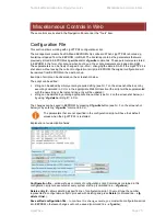
Page 75: ...r 7 on the screenshot below or by executing command in CLI or in the appropriate Web GUI section the script will be supplemented with the new string or the instant string entry will be updated string...

Page 76: ...d on the label net ip remaddr 192 168 205 11 or 192 168 205 10 net ip mask 255 255 255 0 net ip gw 255 255 255 255 default gateway none SNMP trap 255 255 255 255 none 3 restarts the management control...

Page 77: ...vailable licenses shows the list of entered licenses To activate any license select it Add will transform into Activate which should be pressed License key allows entering a license key Entering a lic...

Page 78: ...port for more information about file upload please refer to the respective chapter Updating Software configuration backup files are created by LigoPTP 24 management system The flash disk may store oth...

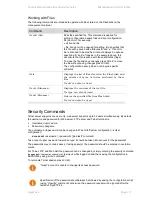
Page 79: ...name Displays the contents of the text file tfs type can also be used tfs del filename Deletes the specified file from Flash disk tfs rm can also be used Security Commands Telnet server supports one u...

Page 80: ...Technical Description Configuration Guide Miscellaneous Controls in Web LigoWave Page 80...

Page 81: ...on file if necessary The file upload can be performed via Ethernet management port using update package via Ethernet management port using FTP via Ethernet management port using TFTP or via RS232 seri...

Page 82: ...ceed as follows 1 Connect the LigoPTP 24 to network or directly to PC 2 Make sure TFTP is running on LigoPTP 24 by default the TFTP is switched off to run the TFTP on LigoPTP 24 connect to LigoPTP 24...

Page 83: ...FTP use the following command tftp i 192 168 205 11 get filename destination_filename where 192 168 205 11 LigoPTP 24 port IP address host filename file to be copied from LigoPTP 24 to PC destination_...

Page 84: ...a connection 2 Type restartcpu and while LigoPTP 24 is booting press any key when boot ini prompt appears This will stop executing script in boot ini file and the LigoPTP 24 will remain in MicroMonito...

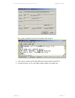
Page 85: ...Software LigoWave Page 85 When upload is complete the following information will be displayed 5 Enter reset command to exit from MicroMonitor mode and restart the LigoPTP 24 6 Proceed with steps 5 and...

Page 86: ...one using digital multimeter which is connected to the RSSI port The output of the RSSI port is DC voltage and varies depending on received signal level The following chart and table shows typical rel...

Page 87: ...on there is a special grounding screw M6 on the front of the unit intended for lightning protection the LigoPTP 24 Full ODU must be grounded using the grounding screw Twin BNC Connector Twin BNC conne...

Page 88: ...Technical Description Configuration Guide Pinouts LigoWave Page 88 Sealed RJ 45 Socket The pinouts of that socket are as follows Figure 54 RJ 45 socket pin numbering 1 2 RX 3 6 TX 4 5 DC 7 8 DC...

Page 89: ...LTW cable connector case P N FOACNR03 FODU 18 pin cable connector hermetically sealed intended for cable connecting to FODU with termination panel or user equipment P N FOACNL01 FODU RJ 45 connector 8...

Page 90: ...0 Item Description 13 15GHz Flexible Waveguide 60cm UBR PBR P N C15WF201 18 23GHz Flexible Waveguide 2ft 6 P N C22WF201 LigoPTP 24 Lightning Protection RJ45 Indoor P N I0ALAI01 Power over Ethernet Sin...

Page 91: ...tion FODU twin BNC RG108A connector for RS 232 console port for FODUs P N FOACNT01 Lightning arrestor for Ethernet patch cable Lightning arrestor for E1 10 pair cable LigoPTP 24 Power over Ethernet In...

Page 92: ...UTP cable cat5 4P outdoor solid P N FOACET02 LigoPTP 24 TP4 terminal power injector w 4E1 P N I0GTP401 RSSI cable for ODU align 1m BNC 2 plug in P N CLGCRS01 Other Available Accessories Test equipmen...

Page 93: ...ommand Line Interface CPU Central Processing Unit CRC Cyclic Redundancy Check DC Direct Current DiffServ Differentiated Services DSCP Differentiated Services Code Point EEPROM Electrically Erasable Pr...

Page 94: ...vice QPSK Quadrature Phase Shift Keying RAM Random Access Memory RSL Received Signal Level RSSI Received Signal Strength Indicator Rx Receive SNMP Simple Network Management Protocol SNR Signal to Nois...

Reviews: