21
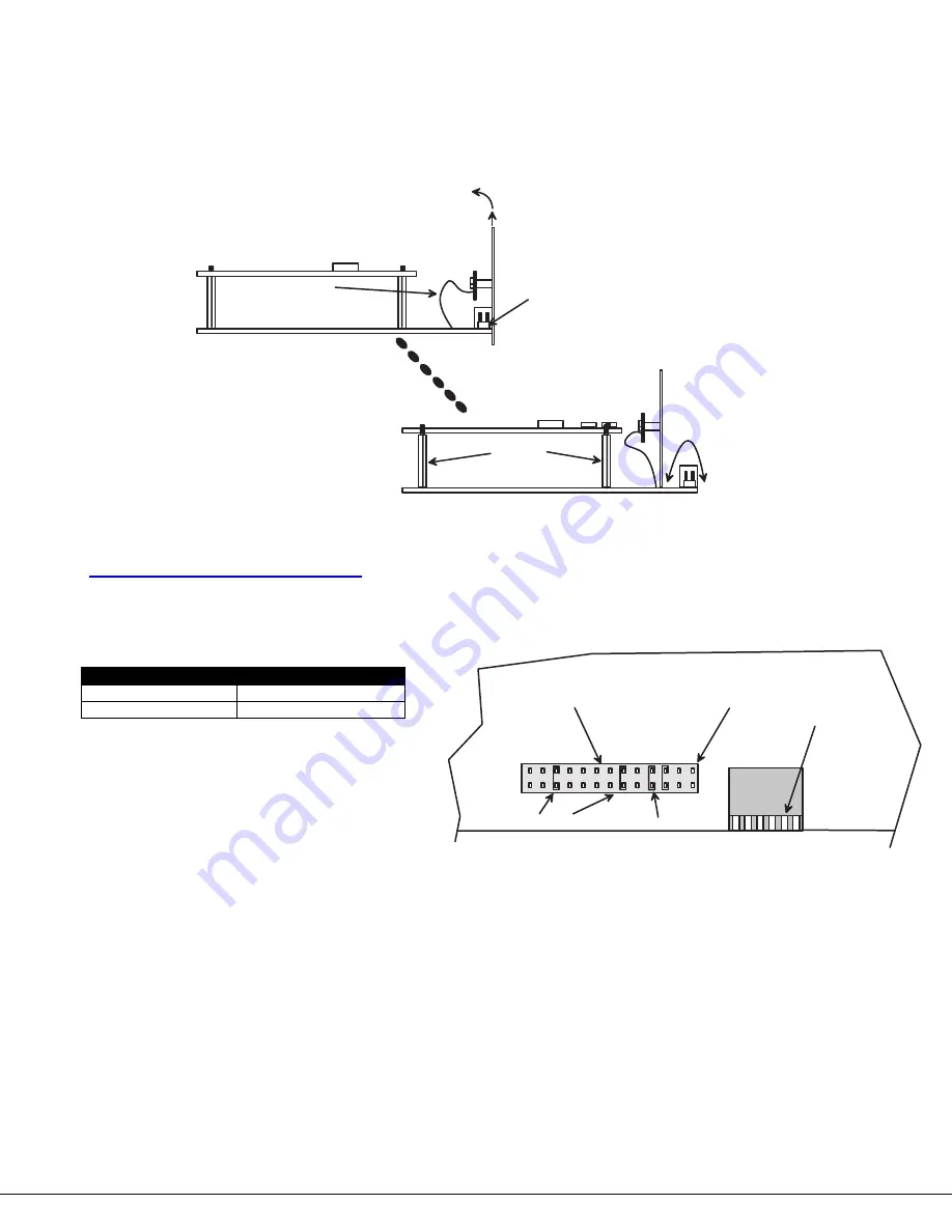
5. Grasp firmly the front panel and slide the front panel up out of the slots in the plastic case that support it.
Once the panel is clear of the case, pivot the panel back approximately 1", just enough to expose the
jumper block. (See Fig. 2
2
.) Be careful not to dislodge the connection of the ribbon connecting the LED
board to the digital board. If it appears to become loose, be sure to reseat the connection before
re-assembly. Now follow the instructions under "CONFIGURING THE JUMPER BLOCK" below.
Figure 22- Get access to jumper block
Configuring The Jumper Block
Once the jumper block is exposed, apply a jumper across the appropriate pins to disable the desired mode(s) according to
the chart below.
Pin Designation
Mode
KCMD
Command Mode*
SCAN
Scan Mode
*Note: Putting a jumper across pins KCMD to
disable Command Mode will also disable
Scan Mode.
Figure 23- Configure the jumper block
Once the desired jumpers are in place, reverse the disassembly process to re-assemble the
USB Wizard
. Do not turn the
power
ON
until the switch has been properly re-assembled.
. . . . a n d s e t b a c k e n o u g h
t o c l e a r j u m p e r b l o c k .
J u m p e r b l o c k
S t a n d o f f s
R i b b o n f r o m L E D
b o a r d t o d i g i t a l b o a r d
L i f t f r o n t p a n e l . . . . .
L
C
D
E
K
C
M
D
B
R
D
C
S
C
A
N
J U M P E R B L O C K
D I P S W I T C H E S
D r a w i n g s h o w s j u m p e r a c r o s s S C A N p i n s , d i s a b l i n g S c a n M o d e .
C o m m a n d M o d e i s s t i l l e n a b l e d .
J U M P E R
D E F A U L T J U M P E R S
D o n o t p u t a j u m p e r h e r e .
T h e L C D f e a t u r e i s n o t
a v a i l a b l e o n t h i s s w i t c h .


