background image

7

CASCADING

The 

USB Wizard

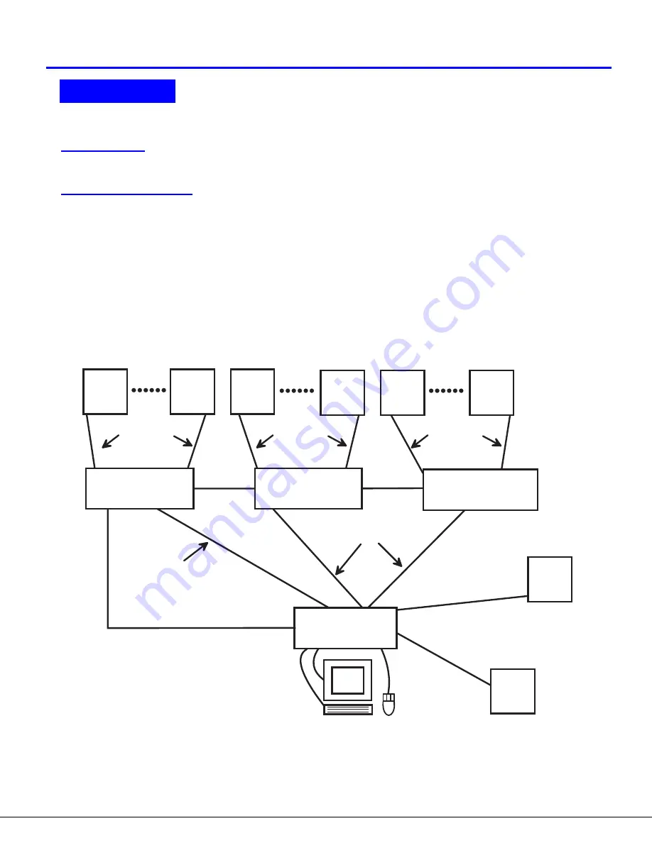
 can be cascaded as shown in Fig. 6 below.


  If 

USB Wizard

 switches are

 being cascaded, configure

the dip-switches accordingly (see Tables 1 and 2 on page 8).

Configuration

All units are configured using the 6-position dip switch (located on the front of each unit) according to the tables on page 8 (1 & 2).

Cascaded Installation

a.    

Configure each dip switch as per the tables on page 8 before proceeding.

b. Using the 15HD video cable ends of a USBVEXT-xx-MM cable, connect the 

USB Wizard

 slave's MONITOR port to the master’s

       VIDEO 1 port.
c. 

Using the USB ends of the same USBVEXT-xx-MM cable, connect one of the USB slave’s USB DEVICES ports to the

       master’s CPU 1 port.

Note:


Only one of the two ports labeled DEVICES on a slave needs to be used in order for cascading to work.

d.    Repeat step b. & c. for each additional slave, keeping in mind that each slave will connect to the next available master’s
       port (i.e. Slave #2 to master’s VIDEO 2 & CPU 2,  etc.)  


See Fig. 7 on page 8.

e.     With a RMT extension cable, connect the master’s DAISY OUT port to slave #2’s DAISY IN port.   Then connect slave #2’s
       DAISY OUT to slave #3's DAISY IN.    Continue until all slaves are connected together.

                                                                Figure 6- Connections for Cascading

.

CASCADING

( s l a v e   u n i t   1 )

( s l a v e   u n i t   2 )

( s l a v e   u n i t   3 )

( m a s t e r   u n i t )

R E X T - S R - x x

R E X T - S R - x x

R E X T - S R - x x

U S B - V E X T - x x M M

U S B V E X T - x x - M M

U S B

C P U

U S B

C P U

U S B

C P U

U S B

C P U

U S B

C P U

U S B

C P U

U S B

C P U

U S B

C P U

U S B V E X T - x x - M M

U S B V E X T - x x - M

M

U S B V

E X T - x

x - M M

U S B - V E X T - x x M M

U S B - V E X T - x x M M

USB Wizard

USB Wizard

USB Wizard

USB Wizard

Summary of Contents for USB-Wizard

Page 1: ...8 User USB Switch INSTALLATION USER GUIDE MAN035 Rev Date 5 6 2003 Zaubzerstrasse 11 81677 Munich Germany Tel 49 0 89 306381 0 Fax 49 0 89 306381 20 www lightwave de USB WIZARD...

Page 2: ...mmunications All rights reserved No part of this publication may be reproduced stored in a retrieval system or transmitted in any form or by any means electronic mechanical photocopying recording or o...

Page 3: ...Control 9 MODES OF OPERATION 9 Basic Command Mode 9 OSD CONTROL 10 Security Option 10 Enabling the Security Feature 10 User Login Mode 11 ADDITIONAL MODES AVAILABLE WITH SECURITY 11 Administration Mod...

Page 4: ...9 User Login screen 11 Figure 10 Administration Mode menu 11 Figure 11 Administrator Password screen 12 Figure 12 User Name List screen 12 Figure 13 System Access List screen 13 Figure 14 Command Mod...

Page 5: ...s Supported USB keyboard with Windows layout USB keyboard with SUN layout USB keyboard with MAC layout USB Mouse up to 3 buttons USB IntelliMouse scrollwheel USB Hub Mouse trak trackball Logitech Cord...

Page 6: ...e or more USB input devices to plug in to the USB The hub has exactly one upstream port with one or more downstream ports which input devices connect to CPU Enclosure that contains the operating syste...

Page 7: ...connecting video cables from CPUs 8 MONITOR 15HD female connector for connection of the user video monitor 9 5VDC connection jack for the AC adapter 10 CPU x USB type B female connector for connection...

Page 8: ...U 8 D E V I C E S C P U 7 C P U 6 C P U 5 C P U 4 C P U 3 C P U 2 C P U 1 5 V D C 2 A V I D E O 8 R V I D E O 7 V I D E O 6 V I D E O 5 V I D E O 4 V I D E O 3 V I D E O 2 V I D E O 1 M O N I T O R D...

Page 9: ...P U 3 C P U 2 C P U 1 5 V D C 2 A V I D E O 8 R V I D E O 7 V I D E O 6 V I D E O 5 V I D E O 4 V I D E O 3 V I D E O 2 V I D E O 1 M O N I T O R D A I S Y O U T D A I S Y I N U S B T y p e B F f e m...

Page 10: ...is directly connected to the USB Wizard USB MAC keyboards with USB Type A female ports built into them are designed as hubs and must be treated as such with respect to the USB Wizard As a result USB...

Page 11: ...DEVICES on a slave needs to be used in order for cascading to work d Repeat step b c for each additional slave keeping in mind that each slave will connect to the next available master s port i e Slav...

Page 12: ...ster Port 1 with an 8 port Slave connected to it will become ports 1 8 Master Unit Port 2 with a second 8 port Slave Unit connected will become port numbers 9 16 All USB Wizard switches must be powere...

Page 13: ...AL described below and on page 11 The two MODE LEDs on the front panel indicate which mode is selected Release the touch switch when the LEDs indicate the desired mode When no mode LEDs are illuminate...

Page 14: ...d Mode from the keyboard using the sequence Ctrl accent key The OSD menu will automatically appear on the monitor in addition to illuminating the Command Mode indicator LED on the USB Wizard This prov...

Page 15: ...on Mode To enter the Administration Mode menu press A from the Maintenance Mode menu page 10 Administration Mode allows the administrator to use the following functions Function Keystroke Change the a...

Page 16: ...enu The User Name List displays the list of users and provides control for adding new users up to 24 changing or assigning user passwords and changing access rights for any given user User names may b...

Page 17: ...and connect to them using that name from a single keyboard and mouse The OSD is positioned on the user s monitor displaying 8 CPU names at a time The screen can be used for switching as well as editi...

Page 18: ...nction Ports listed on the screen can be selected by moving the cursor onto that port and clicking Clicking twice on a selected port will switch to that port and exit Command Mode To change the displa...

Page 19: ...ode press Ctrl E from the Command Mode menu Edit Mode enables the user to modify the names of the CPUs connected to the switch Names of CPUs can be up to 12 characters in length When in Edit Mode mult...

Page 20: ...n search name Figure 17 Search Mode screen Add a character to the search string and select the best matching CPU name Exit Search Mode return to Command Mode Switch to selected port Maintenance Mode T...

Page 21: ...he Command Mode menu see page 14 Help Mode displays a list of commands with a short explanation of their function These lists are organized in pages for each mode i e COMMAND EDIT and SEARCH The follo...

Page 22: ...ity except Application Key Apple Pro Keyboard Extra keys emulation Extra Keys not supported Eject Mute Volume Volume Full functionality Sun Mouse Full functionality Full functionality Full functionali...

Page 23: ...i n d o w s L o g o K e y W i n d o w s L o g o K e y E n t e r R e t u r n A l t G r a p h S h i f t S h i f t C o n t r o l T a b C a p s l o c k A l t B a c k s p a c e N u m L o c k H e l p S t o...

Page 24: ...disassemble the unit to gain access to the jumpers block For models in a plastic case 1 The USB Wizard must be completely disconnected from all computer components 2 Unplug the USB Wizard from the el...

Page 25: ...KCMD Command Mode SCAN Scan Mode Note Putting a jumper across pins KCMD to disable Command Mode will also disable Scan Mode Figure 23 Configure the jumper block Once the desired jumpers are in place r...

Page 26: ...each CPU and the switch Verify that keyboard and video connect from each CPU to matching ports After reconnecting CPU may need to be re booted in order to sense the monitor connection PROBLEM No Mouse...

Reviews: