3. Product Overview
DVIDL-OPT series – User's Manual
8
Product Overview
The following sections are about the physical structure of the device, input/
ç
ç
ç
ç
ç
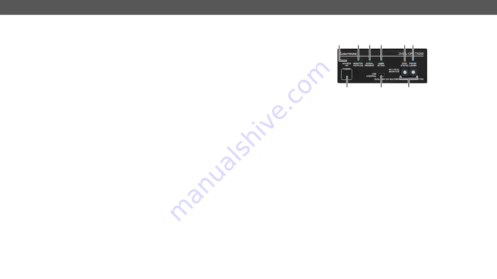
3.1. Front View (Transmitter)
2 3 4
1
5 6
7
8
9
1
5V LED
The LED indicates if a DVI source is connected to the unit, it is powered
on and sends 5V signal to Pin 14 of the input DVI connector.
2
Monitor Hotplug
LED
The LED indicates if a display device (or repeater, etc.) is connected to
the corresponding DVI output and it sends a valid Hot Plug Signal on
Pin 16 through the DVI cable.
3
Signal Present LED
Indicates when a valid DVI signal is detected on the DVI INPUT
connector.
4
Laser Active LED
Indicates when the laser driver is enabled to help avoid accidentally
looking into the laser beam.
5
EDID Status LED
Shows the status of the selected EDID and gives feedback about EDID
learning. See more information in the
6
Learn button
Stores the EDID of the display device attached to the OUTPUT. See
7
Power LED
Power LED lights green when the unit is powered on. It does not indicate
whether the device is operating properly.
8
USB connector
Advanced EDID management (in LDC software) and firmware upgrade
are available via the USB interface. Use an USB cable with mini-B male
connector.
9
EDID rotary
switches
The rotary switches select one of the EDID memory addresses. Use
a flat head screwdriver that fits into the actuator. Avoid the use of
keys, coins, knives and other sharp objects because they might cause
permanent damage to the rotary switches. See more information about
section.


