Page 10 / 29
The TMDS Reclocking circuit eliminates the following errors:
Intra-pair skew:
skew between the + and - wires within a differential wire pair (e.g.
Data2- and Data2+). It’s caused by different wire lengths or
slightly different wire construction (impedance mismatch) in DVI
cable. It results in jitter.
Jitter:
signal instability in the time domain. The time difference between
two signal transitions should be a fix value, but noise and other
effects cause variations.
Noise:
electromagnetic interference between other electronic devices
such as mobile phones, motors, etc. and the DVI cable are
coupled onto the signal. Too much noise results in increased
jitter.
Info
TMDS Recklocking technology does not eliminate Inter-pair skew.
2.7.
Dual link DVI signal
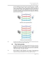
The dual link DVI interface can operate in either single link or dual link mode. The
chosen mode depends on the pixel clock frequency of the signal and it is selected
by the hardware automatically. For pixel clock frequencies lower than 165 MHz,
single link mode is selected. For higher pixel clock frequencies (up to 330 MHz),
dual link mode is selected. It is important to know that pixel clock frequency is not
the same as TMDS clock frequency when it comes to dual link DVI.
The pixel clock frequency in single link transmission is a 10
th
part of the data rate.
The maximum data rate of single link transmission is 1.65 Gbps per TMDS channel
and the maximum pixel clock frequency is 165 MHz. In this case the pixel clock
frequency equals the TMDS clock frequency.
The pixel clock frequency in dual link transmission (when in dual link mode) is a 5
th
part of the data rate. The maximum data rate of dual link transmission is still
1.65 Gbps per TMDS channel but the maximum pixel clock frequency is 330 MHz.
In this case the pixel clock frequency is two times the TMDS clock frequency.


