background image


9. Technologies 

DVI-OPT-220-Pro series  – User's Manual 

35

9.3. 

Serial Management

9.3.1. 

General Information 

There are two types of devices in general serial communication:


Data Terminal Equipment: 

Data Terminal Equipment (DTE) is an end instrument that converts user 

information into signals or reconverts received signals. Typical DTE devices: computers, LCD touch 
panels and control systems.


Data Circuit-terminating Equipment:

 Data Circuit-terminating Equipment (DCE) is a device that sits 

between the DTE and a data transmission circuit. It is also called data communication equipment and 

data carrier equipment. Typical DCE devices: projectors, industrial monitors and amplifiers.

Among others the pin assignment is different between DTE and DCE.

DTE

DCE

Pin 2:

RD

TD

Pin 3:

TD

RD


   RD

: Received Data (digital input) 


TD: 

Transmitted Data (digital output)

Different type of serial cables must be used between different serial devices.

DTE

DCE

DTE

Null-modem

Straight

DCE

Straight

Null-modem*

* In general contact DCE with DCE by tail-circuit serial cable.

9.3.2. 

Types of Serial Cables

Straight Serial Cable

Null-modem Serial Cable

Straight pin-outs both ends.

Straight pin-out at the one end and cross 

pin-out at the other end (interchange lines 

of TX and RX).

Serial cables between devices may have male or female plugs and their type may be straight or null-modem 

in usual.

ATTENTION! 

The cable type does not depend on the plug type.

9.3.3. 

RS-232 Signal Transmission over Lightware Extender Devices

The following examples describe the detailed integration of Lightware devices between different RS-232 pin 

assignment units.

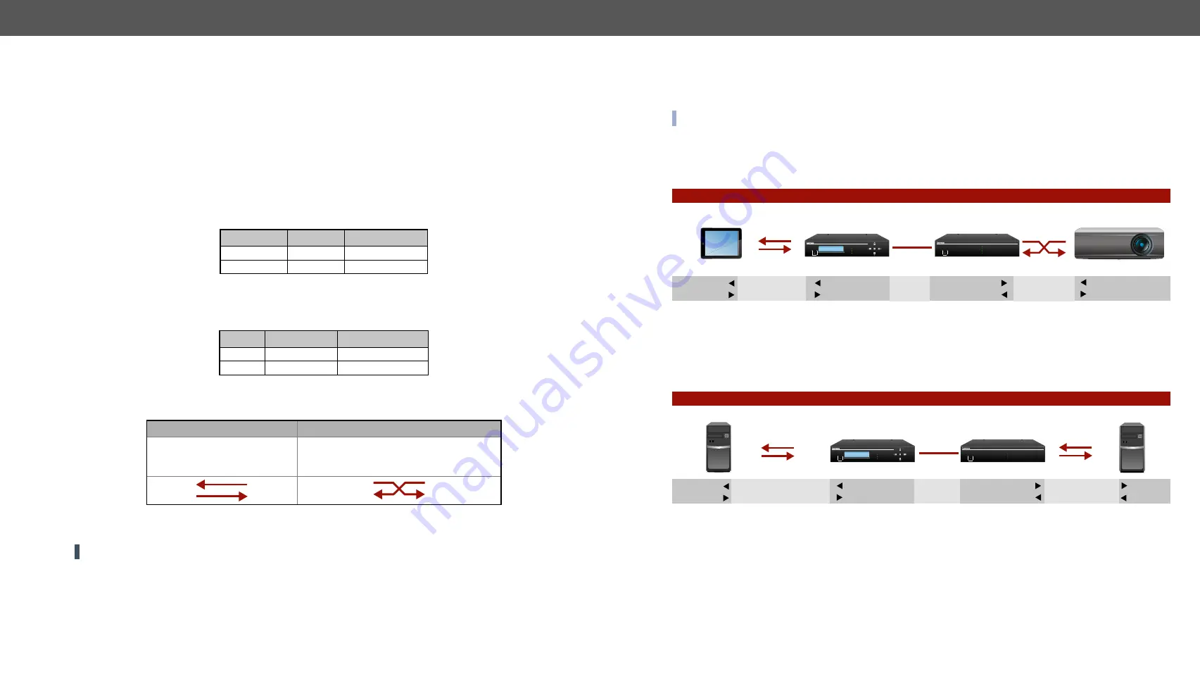
INFO: DVI-OPT-220-Pro series extenders are DCE units (according to their pinouts) with female plugs. 

Extending RS-232 between DTE and DCE Third-party Devices

Connect straight serial cable between controller system (DTE) and the transmitter (DCE) and null-modem 

serial cable between receiver (DCE) and projector (DCE).

RS-232 Connection Example between a Controller System and a Projector

Extending RS-232 between DTE and DTE Third-party Devices

Connect straight serial cable between controller system (DTE) and the transmitter (DTE) and  straight serial 

serial cable between receiver (DTE) and computer (DTE).

RS-232 Connection Example between Two Computers

Transmitter

Controller system

Projector

Female - Male

Male - Male

Transmission 

interface

Straight serial 

cable

Null-modem

serial cable

DCE

Pin 2: RD

Pin 3: TD

Receiver

DCE

Pin 2: TD

Pin 3: RD

Pin 2: TD

Pin 3: RD

DTE

DCE

Pin 2: TD
Pin 3: RD

POWER

SOURCE CONNECTED (pin14 +5V)

LASER ACTIVE

DVI INPUT SIGNAL PRESENT

ENTER

DVI Multimode Fiber Transmitter

DVI-OPT-TX220-Pro

DVI Multimode Fiber Receiver

DVI-OPT-RX220-ST-Pro

MONITOR 2 HOTPLUG

DVI SIGNAL PRESENT

MONITOR 1 HOTPLUG

GREEN: LASER DETECTED

RED BLINKING: LOW LASER LEVEL

POWER

Transmitter

Computer

Computer

Female - Male

Male - Female

Transmission 

interface

DCE

Pin 2: RD

Pin 3: TD

Receiver

DCE

DTE

DTE

Pin 2: RD

Pin 3: TD

Pin 2: TD

Pin 3: RD

Pin 2: TD

Pin 3: RD

Straight serial 

cable

Straight serial 

cable

POWER

SOURCE CONNECTED (pin14 +5V)

LASER ACTIVE

DVI INPUT SIGNAL PRESENT

ENTER

DVI Multimode Fiber Transmitter

DVI-OPT-TX220-Pro

DVI Multimode Fiber Receiver

DVI-OPT-RX220-ST-Pro

MONITOR 2 HOTPLUG

DVI SIGNAL PRESENT

MONITOR 1 HOTPLUG

GREEN: LASER DETECTED

RED BLINKING: LOW LASER LEVEL

POWER

 

Summary of Contents for DVI-OPT-RX220-Pro

Page 1: ...DVI OPT TX220 Pro DVI OPT TX220 ST Pro DVI OPT RX220 Pro DVI OPT RX220 ST Pro User s Manual Fiber Multimedia Extender ...

Page 2: ... the apparatus is recommended to securely attach to the floor wall or mount in accordance with the installation instructions The apparatus shall not be exposed to dripping or splashing and that no objects filled with liquids such as vases shall be placed on the apparatus No naked flame sources such as lighted candles should be placed on the apparatus CAUTION AVIS RISK OF ELECTRIC SHOCK DO NOT OPEN...

Page 3: ... If you clicked on a link previously you can go back to the source page by clicking the button Navigate to the Table of Contents Step back one page Step forward to the next page Document Information Allpresentedfunctionsrefertotheindicatedproducts Thedescriptions have been made during testing these functions in accordance with the indicated Hardware Firmware Software environment Item Version Light...

Page 4: ... REFERENCE 23 6 1 LW2 Protocol Description 23 6 2 General LW2 Commands 23 6 2 1 Query Control Protocol 23 6 2 2 View Product Type 24 6 2 3 View Serial Number 24 6 2 4 View Firmware Version of the CPU 24 6 2 5 View Installed Board s 24 6 2 6 View Firmware for all Controllers 24 6 2 7 All Port Status 24 6 3 EDID Management 25 6 3 1 View Emulated EDID on the Input 25 6 3 2 Save EDID to User Memory Le...

Page 5: ...e details see the Application Example of Break out Connector section Local Monitor Output User can attach a local monitor to observe the video signal sent through the fiber optical cable The resolution and clock frequency are the same on DVI and fiber optical connectors no internal scaling or conversion is applied 1 1 Description Lightware DVI OPT TX220 Pro is a Single Link DVI optical transmitter...

Page 6: ... LAS ER DET ECT REC EIVE R ACT IVE SIGN AL PRE SEN T MX DV I O PT IB S T 4 CH DU AL LIN K DV I INP UT BO AR D MX DV IDL IB LC 50 1 25 MUL TIM ODE LAS ER DET ECT REC EIVE R ACT IVE SIGN AL PRE SEN T L D R A SIGN AL IN1 IN2 IN7 IN8 IN5 IN6 IN3 IN4 IN1 IN2 IN7 IN8 IN5 IN6 IN3 IN4 LAS ER DET ECT REC EIVE R ACT IVE SIGN AL PRE SEN T MX DV I O PT IB S C OU T1 OU T2 OU T7 OU T8 OU T5 OU T6 OU T3 OU T4 8C...

Page 7: ...on the board Step 4 Loosen the screws a little on the bracket and adjust the unit to line up with the front of the board 2 1 3 Rack Shelf Mounting Step 1 Turn the unit upside down Step 2 Put the rack shelf upside down on the unit and position it to get the mounting holes aligned Step 3 Fasten the unit on the rack shelf with the provided screws Step 4 Mount the rack shelf in the rack Standard rack ...

Page 8: ...wering options in the next section WARNING Please do not look directly into the fiber optical connector if the cable is connected to the transmitter only and the laser is active 2 3 Powering Options When building an electronic system make sure that all of the devices are powered down before connecting them Powered on devices may have dangerous voltage levels that can damage sensitive electronic ci...

Page 9: ... Menu Operations section for more information Status LEDs POWER green on The transmitter unit is powered and ready to use off The transmitter unit is NOT powered on LASER ACTIVE green on It gives feedback about the operation of the optical module laser is enabled that means the laser radiates invisible waves Avoid direct eye contact with the optical connectors off Laser module is not active laser ...

Page 10: ... DVI and Neutrik connectors no internal scaling or conversion is applied to the signal See DVI Inputs and Outputs section for more information 5 Laser Active LED on It gives feedback about the operation of the optical module laser is enabled that means the laser radiates invisible waves Avoid direct eye contact with the optical connectors off Laser module is not active laser is disabled on the out...

Page 11: ...xel clock frequency are the same on both DVI connectors no internal scaling or conversion is applied to the signal 3 Alarm outputs DVI signal detection and laser detection signals with ground reference are available on a 3 pole Phoenix connector See Alarm Outputs Receiver section for more information 4 Serial port 9 pole D SUB female connector for serial RS 232 communication see RS 232 Control Por...

Page 12: ...controlled through industry standard 9 pin D SUB female connector located on the rear panel of the unit Please use a standard RS 232 Male to Female cable straight through D sub connector pin assignment for standard RS 232 Pin nr Pinout 1 NC non connected 2 TX data transmit output 3 RX data receive input 4 DTR Internally connected to Pin 6 5 GND signal ground shield 6 DSR Internally connected to Pi...

Page 13: ... Application Example of Break out Connector Using this feature it is possible to transmit two different A V signal from one transmitter pair to another receiver pair with only one Neutrik opticalCON DUO cable See the application example below Transmitter Unit DVI OPT TX220 Pro The transmitter s laser driver sends the signal through Channel A Channel B is directly connected to the break out connect...

Page 14: ...If needed use the left and right buttons to select the EMULATED EDID menu The currently emulated EDID is shown Three screens toggle automatically showing the preferred resolution the name of the display and a three letter abbreviation assigned to the manufacturer Lightware factory presets have LWR as the manufacturer 4 2 2 Learning EDID The EDID of the display device that is attached to the local ...

Page 15: ...nu Step 2 Use the up and down buttons to select a filled memory slot Hold down the up and down buttons to scroll faster Three screens toggle automatically showing the preferred resolution the name of the display and a three letter abbreviation assigned to the manufacturer Step 3 Press ENTER to delete selected EDID then use the up and down buttons to change YES NO Step 4 Press Enter to execute YES ...

Page 16: ... After the installation the Windows and the Mac application has the same look and functionality This type of the installer is equal with the Normal install in the case of Windows and results an updateable version with the same attributes Mount the DMG file with double clicking on it and drag the LDC icon over the Applications icon to copy the program into the Applications folder If you want to cop...

Page 17: ...are connected via serial port Step 5 The device name and serial number can be inquired by pressing the query button next to the appropriate COM port Step 6 Select the device and click on the Connect button 5 3 I O Parameters Menu After connecting to the device this menu appears by default showing the current state of input and output ports The port bar on the right side shows the available input a...

Page 18: ...es are reloaded to the input 5 4 EDID Menu Advanced EDID Management can be accessed by selecting the EDID menu There are two panels left one contains Source EDIDs right one contains Destination slots where the EDIDs can be emulated or copied Control buttons Export Exporting an EDID save to a file Executing EDID emulation or copying Transfer button Import Importing an EDID load from a file Delete s...

Page 19: ...y EDID from the User Factory Dynamic EDID lists can be copied to the user memory Emulated EDID list E1 the currently emulated EDID for the input The source column displays the memory location that the current EDID was routed from The source reads the EDID from the Emulated EDID memory on the input port There are two types of emulation static and dynamic Static EDID emulation an EDID from the Facto...

Page 20: ...isplays it as readable information to the user All descriptors can be edited and saved in an EDID file or uploaded to the User memory For more details about EDID Editor please visit our website www lightware com and download the EDID Editor User s Manual EDID Editor Window 5 4 5 Creating an EDID Since above mentioned Advanced EDID Editor needs more complex knowledge about EDID Lightware introduced...

Page 21: ... status Step 1 Press the big red Download report button on the Log tab in Settings menu Step 2 A Save as dialog box appears Select the place where you want to save the report file The default file name can be changed Step 3 LDC collects the needed information This may take up to 5 minutes Step 4 When the process is finished the folder is opened where the file was saved The report contains the foll...

Page 22: ...ands are automatically surrounded by framing brackets as a default setting Every sent command is red colored and gets a prefix Received responses are blue colored and starts with Commands can be sent by pressing enter or the Send button The timecode in every row shows the exact time when the command was sent or the response received If the Command framing checkbox is unchecked you can send multipl...

Page 23: ...escription This command queries the active protocol for the used control interface INFO The response shows only the active protocol for the interface that was used to send the command Format Example Command P_ P_ Response CURRENT PROTOCOL protocol CrLf CURRENT PROTOCOL 1 CrLf Explanation The extender communicates with Lightware protocol 1 Format Explanation in Input number in 1 or 2 digit ASCII fo...

Page 24: ...ards Format Example Command is is Response SL 0 MB_DESC CrLf SL END CrLf SL 0 DVI OPT TX220 PRO SCH_3 2 PCB_3 2 SL END CR LF Explanation The device reports its motherboard slot 0 6 2 6 View Firmware for all Controllers Description Shows the firmware versions of all installed controllers Format Example Command FC fc Response CF DESC CrLf CF DESC CrLf CF END CrLf CF DVI OPT TX220 PRO FW 1 1 8 CF END...

Page 25: ... all inputs but since the transmitter has one input the result will be the same as typing E1 loc2 Fxx or Uxx Static EDID routing occurs In this case the extender will keep the same EDID on the input until it is changed with another command loc2 Dxx Dynamic EDID routing occurs In this case the extender will follow the EDID changes on the output Every time a different EDID is recognized on the outpu...

Page 26: ...00 CrLf Legend B1 B256 are space separated hex characters represented in ASCII format Explanation Full EDID from memory location F1 is downloaded 6 3 7 Upload EDID Content to a Location Description EDID hex bytes can be written directly to the user programmable memory locations Sequence Step 1 Prepare the extender to accept EDID bytes to the specified location loc with command WL loc Step 2 Extend...

Page 27: ...put Response E_S_C CrLf E_S_C CrLf Explanation When a new monitor is connected to an output port its EDID is read The message from the extender shows that an EDID has changed INFO The extender stores the last attached display device s EDID connected to the local monitor output After disconnecting this device its EDID is still present at the extender s memory therefore no status change message is i...

Page 28: ...on See in section Command View Emulated EDID on the Input 6 3 1 VEDID Save EDID to User Memory Learn EDID 6 3 2 loc1 loc2 Change EDID on Input 6 3 3 loc1 loc2 Watch EDID Validity Table 6 3 4 WV View EDID Header 6 3 5 WHD2 Download EDID Content from a Location 6 3 6 WEF1 Upload EDID Content to a Location 6 3 7 WL loc Delete EDID from Memory 6 3 8 DE loc Restart the Extender 6 3 9 RST Extender Initi...

Page 29: ...ettings Set to factory defaults Output port settings Set to factory defaults 7 1 Short Instructions Step 1 GetthefirmwarepackandtheLightwareBootloaderapplication Step 2 Install the Lightware Bootloader application Step 3 Establish the connection between the computer and the device s Step 4 Start the Lightware Bootloader and follow the instructions 7 2 Install the Bootloader Step 1 Run Installer_LW...

Page 30: ...firmware s Click UPGRADE SELECTED FIRMWARES button on the left side A confirmation message appears After clicking the YES button the selected controller is being reprogrammed with the firmware you selected If you select a file that doesn t fit for the selected controller you will get an information message about which file is wrong If you selected a controller to upgrade but you had not selected a...

Page 31: ...ure that the proper port is selected 3 3 Cable quality problem Due to the high data rates high quality cables must be used It is recommended to use OM3 or OM4 fiber cables 10 3 Endface surface of the fiber optical cable became contaminated Use special fiber optical cable cleaning equipment to clean it carefully Display is not capable of receiving the sent video format Try emulating your display de...

Page 32: ...her printed somewhere on the box or you can query it in the Device Controller software or on the built in website Firmware versions of the devices please note that there may be multiple CPUs or controllers in the device and we need to know all of their firmware versions a screenshot is the best option Cable lengths and types in our experience it s usually the cable Patch panels gender changers or ...

Page 33: ...erent EDID on an input port of the Lightware device to have a different resolution but nothing happens Solution Some graphics cards and video sources read out the EDID only after power up and later they do not sense that EDID has been changed You need to restart your source to make it read out the EDID again 9 1 2 Advanced EDID Management Each DVI sink e g monitors projectors plasma displays etc m...

Page 34: ...r skew Skew between the and wires within a differential wire pair e g Data2 and Data2 It s caused by different wire lengths or slightly different wire construction impedance mismatch in DVI cable It results in jitter Intra pair skew Inter pair skew Skew between two differential wire pairs in a cable It is caused by different wire pair lengths or different number of twists in the DVI cable Too much...

Page 35: ...f Lightware devices between different RS 232 pin assignment units INFO DVI OPT 220 Pro series extenders are DCE units according to their pinouts with female plugs Extending RS 232 between DTE and DCE Third party Devices Connect straight serial cable between controller system DTE and the transmitter DCE and null modem serial cable between receiver DCE and projector DCE RS 232 Connection Example bet...

Page 36: ... Baud rate 9600 Optical Port Fiber type 50 125 SC Multimode fiber Laser wavelengths 4ch CWDM 778 800 825 850 nm Laser class specification Class 3R Transmitter output OMA 6 25 dBm worst case Receiver OMA sensitivity 14 25 dBm worst case Optical loss budget 8 dBm worst case Transmission distance 2500 meters using OM3e type fiber OMA Optical Modulation Amplitude Digital video signal Standard DVI 1 0 ...

Page 37: ...40 x 480 59 94 Hz F32 720 x 480 59 92 Hz F33 1440 x 576i 50 6 Hz F34 720 x 576p 50 0 Hz F35 1280 x 720p 50 0 Hz F36 1280 x 720p 60 0 Hz F37 1920 x 1080i 50 3 Hz F38 1920 x 1080i 50 0 Hz F39 1920 x 1080i 60 5 Hz F40 1920 x 1080 24 0 Hz F41 1920 x 1080 24 99 Hz F42 1920 x 1080 30 0 Hz F43 1920 x 1080 50 0 Hz F44 1920 x 1080 49 99 Hz F45 1920 x 1080 60 0 Hz F46 2048 x 1080 49 99 Hz F47 2048 x 1080 50...

Page 38: ...IVE DVI INPUT SIGNAL PRESENT ENTER DVI Multimode Fiber Transmitter DVI OPT TX220 Pro 42 2 221 A B DVI INPUT LOCAL MONITOR OUTPUT 100 240 V AC FUSE F 1 A 50 60 Hz 0 7 A Remote power for receiver DC OUT 15V GND Remote power for receiver DC OUT 15V GND LASER ACTIVE FIBER OUTPUT A 50 125 MULTIMODE RoHS Made in EU HU B A LOCAL CONTROL RS 232 Laser Radiation 850 nm Class 3 181 Left View Bottom View 17 1...

Page 39: ... stated warranty and procedures will not apply to any product that has been 2 1 Modified repaired or altered by anyone other than a certified Lightware engineer unless expressly agreed beforehand 2 2 Used in any application other than that for which it was intended 2 3 Subjected to any mechanical or electrical abuse or accidental damage 2 4 Any costs incurred for repair replacement of goods that f...

Reviews: