LightSpeed Technologies CAT805iX User Manual Download Page 11

11

1. Overview

2. Setup & Use

3. Optional 


Accessories

4. T

roubleshooting

5. W

arranty

, Safety 


& Specifications

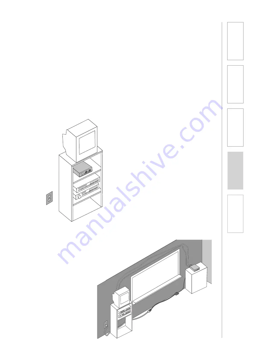
First, find a suitable location to set-up the CAT 805iX preamp. It is best to put the 
preamp in a stable location near the amplifier to be used.

Media Cabinet Set-up

SECTION 2:  

SET-UP & USE

1. LOCATION OF THE  RECEIVER

Avoid Separated Set-ups

Ideally the preamp should be located 
very near the amplifier being used. 
Avoid long distances when possible 
to minimize wire runs and installation 
hassle.

Summary of Contents for CAT805iX

Page 1: ...U s e r M a n u a l Infrared Wireless Microphone System 805iX...

Page 2: ......

Page 3: ...REDMIKE 18 Step 5 Operating the REDMIKE 19 Using REDMIKE to Amplify External Audio Equipment SECTION 3 20 REDMIKE VC Optional Accessories 20 Controls and Connections 21 Charging 21 Initial Set Up 22...

Page 4: ...anty Safety Specifications Preamp Power Supply SECTION 1 OVERVIEW SYSTEM COMPONENTS AND UNPACKING The standard configuration of the CAT 805iX will contain ISR Infrared Sensor Receiver and Cable Chargi...

Page 5: ...ng bracket CA P5E50 50 plenum rated Cat 5e cable RMT REDMIKE classroom microphone with battery BA NH2A27 AA NiMH rechargeable sensing battery for REDMIKE AC RMLC2 REDMIKE lavaliere cord BC RMCC REDMIK...

Page 6: ...INDICATOR Press this button to turn the CAT 805iX ON pushed in or OFF When the POWER is switched on the blue LED indicator will light 2 AUDIO INDICATORS These lights flash red when audio voice from th...

Page 7: ...input on an amplifier 3 CH B OUTPUT This balanced output sends the audio from only the microphone set to CH B to an input on an amplifier 4 CH A OUTPUT This balanced output sends the audio from only...

Page 8: ...These lights glow when the corresponding microphone set to channel A or B is turned on and transmitting A steady light indicates a strong signal 3 SENSOR OUT Connect the Cat 5 sensor cable to this co...

Page 9: ...able protective tab before use NOTE do not attempt to remove the tab without first opening the compartment door as it may tear leaving fragments 5 AUDIO MICROPHONE INPUT Use this input to plug in a la...

Page 10: ...light indicates that no battery is sensed REDMIKE Yellow Protective Tab may not have been completely removed see page 5 item 4 A blinking Green LED means a non Lightspeed battery has been installed p...

Page 11: ...CAT 805iX preamp It is best to put the preamp in a stable location near the amplifier to be used Media Cabinet Set up SECTION 2 SET UP USE 1 LOCATION OF THE RECEIVER Avoid Separated Set ups Ideally t...

Page 12: ...Microphone System The ISR should be as high as possible in the room the ceiling is the best location centered along the longest wall in the room When possible use a conduit to protect the wires not i...

Page 13: ...ab around the other side of the t bar c Repeat with the other side of the bracket so it is connected at all four points 2 Slide the ISR onto the bracket until it clicks into place a Guide the mounting...

Page 14: ...5iX preamp securing it along with way using surface raceway where possible 3 Slide the ISR onto the bracket until it clicks into place a Guide the mounting rails onto the bracket oriented as pictured...

Page 15: ...power supply to the 24VDC input 3 Connect the AC adapter end of the supply into a wall outlet 1 Ensure the power is still switched OFF 2 Check the connection from the ISR to the CAT 805iX Ensure the s...

Page 16: ...er b CH A CH B OUTPUTS connect to these outputs if you wish to use the amplifier to control each microphone channel individually 3 Insert the stripped wires into the marked openings on the euro block...

Page 17: ...ached A blinking light indicates a charging or sensing error See Troubleshooting section for more information REDMIKE incorporates alkaline protection into the microphone design Always use a Lightspee...

Page 18: ...l voice slowly increase the volume of the corresponding channel on the CAT 805iX until your voice is barely audible Each REDMIKE has its channel pre set to either A or B as indicated on the back of th...

Page 19: ...plify the external audio equipment so the teacher s volume on the Channel A teacher mike does not have to be adjusted To determine which REDMIKE is set to Channel B you can look at the switch on the b...

Page 20: ...ery should only be replaced by a Lightspeed AA rechargeable sensing battery part BA NH2A27 4 YELLOW PROTECTIVE TAB Slide the battery compartment door and remove this disposable protective tab before u...

Page 21: ...e instructions for the REDMIKE See page 17 and follow the same instructions for the REDMIKE to setup the REDMIKE VC NOTE A nominal volume level must be set on the CAT 805iX before adjusting controls o...

Page 22: ...harged A RED light indicates a charge is needed 4 EXTERNAL MICROPHONE INPUT MIC Use the 3 5mm MIC jack for the optional TK 250 headset microphone part MC TK250LTM 5 AUXILIARY AUX Plug a laptop MP3 pla...

Page 23: ...he CHARGER jack on the LT 71 1 Ensure that the LT 71 is turned OFF 2 Make sure the cradle charger is plugged into a wall outlet Connect one end of the charging cable into the jack labeled CHARGER on t...

Page 24: ...operating channel to B 3 Slip the LT 71 with lanyard around the neck and position the top of the microphone just below the collarbone NOTE Positioning of the LT 71 is critical for proper volume adjus...

Page 25: ...l When charging the light glows red 3 AUDIO INPUT plug a laptop MP3 player or other audio device into this jack to wirelessly transmit the audio signal to be played through the system 4 CHANNEL SELECT...

Page 26: ...he CHARGER jack on the REDMIKE Share 1 Ensure that the REDMIKE Share is turned OFF 2 Make sure the cradle charger is plugged into a wall outlet Connect one end of the charging cable into the jack labe...

Page 27: ...Grip the barrel in the center section Avoid covering the infrared emitters just below the microphone grille This could interrupt signal transmission 4 While speaking in a normal voice increase the B V...

Page 28: ...olume on the classroom audio system you will also be changing the volume for your second microphone Return the CH B volume knob to the original position before turning the second microphone back on 2...

Page 29: ...r instructional technologies to be clearly heard throughout the classroom IRMC Infrared Media Connector MC TK250M Noise canceling headset microphone AC TCC7 Charging cable for REDMIKE Share and LT71 P...

Page 30: ...lume or feedback Ensure microphone is positioned appropriately just below the collar bone Check volume level on the amplifier If the volume is too high feedback will occur Adjust accordingly Adjust th...

Page 31: ...te amplification approximately 5 10 dB above ambient room noises Avoid wearing jewelry that may rub or bump against the microphone Turn the REDMIKE off during private conversations with a student pare...

Page 32: ...nt to the customer to minimize downtime Customers will receive the exchange product s or component s within 2 3 days A prepaid return label will be included with exchanged products so original malfunc...

Page 33: ...cian for replacement of the obsolete outlet 10 Protect the power cord from being walked on or pinched particularly at plugs convenience receptacles and the point where they exit from the apparatus 11...

Page 34: ...the following European Union Directives 89 336 EEC 92 31 EEC 93 68 EED and 2004 108 EC Electromagnetic Compatibility Directives Lightspeed Technologies launched a formal product recycle program in Eu...

Page 35: ...er 1 year warranty 1 AA NiMH Rechargeable Sensing Battery Audio Input 3 5 mm Dimensions W x D x H 0 9 x 1 0 x 3 5 Weight 2 1 oz LT 71 LightMic Audio Distortion 1 Built in Microphone Unidirectional Ele...

Page 36: ...LIGHTSPEED TECHNOLOGIES 11509 SW HERMAN ROAD TUALATIN OR 97062 TOLL FREE 800 732 8999 PHONE 503 684 5538 FAX 503 684 3197 LIGHTSPEED TEK COM MN0234US01 2...

Reviews: