LightProcessor Paradime, all variants, version 21, September 2003
Page 11
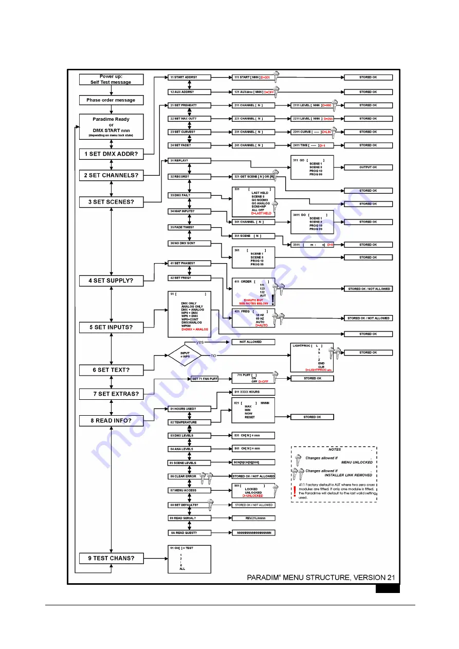
Fig. 19
Page 1: ...INSTALLATION AND OPERATING MANUAL Version 21 September 2003 all variants...
Page 2: ......
Page 3: ...HR EINES STROMSCHLAGES ATENCION PELIGRO DE SHOCK ELECTRICO CAUTION REFER TO INSTRUCTION MANUAL ATTENTION REFEREZ VOUS AU MODE D EMPLOI ACHTUNG BEACHTEN SIE BITTE DIE BEDIENUNGSANLEITUNG ATENCION REFER...
Page 4: ...and user options 6 Diagram menu structure 11 Reference Section Maintenance 12 System Messages 13 Specification 14 Spares List 15 Warranty Statement Repairs Procedures 16 CONTENTS Rackmount Models Inst...
Page 5: ...articularly regarding safety with all regulations in force in the country in which the product is being used 1 Unpack the Product Ensure you do not throw away any accessories packed separately in the...
Page 6: ...support brackets using the M6 10mm bolts supplied 9 Slide the chassis partially back into the lid section 10 Proceed to page lll This product is designed to be mounted vertically in an upright attitu...
Page 7: ...n be seen in the top right corner adjacent to the transformer and electronics control fuse Change the supply links as shown in figs 5A and 5B Change the electronics protection fuse to the correct type...
Page 8: ...of a wall mount Paradime Draw in the input and output cables Make connections as shown below Secure the earth conductor to the earth block For single phase supplies Where the Paradime is to be used s...
Page 9: ...tted and wired to multi pole connectors are available as accessories for fitting to all models of the dimmer SERVICE PLATE TYPES Connector Type Connectors Part Number Blank 0 MPARADIM B 19 pin Ceep So...
Page 10: ...age 9 of this manual Press the 4 the display will show 41 SET PHASES Press the 4 the display will show 411 SET ORDER auto factory setting Pressing the up or down arrow keys will change the setting wit...
Page 11: ...that the appropriate protocol must be selected in software see menu 51 WALLMOUNT STANDARD WITH HARDWIRED CONNECTIONS When making connections note that the black headers may be unplugged from the circ...
Page 12: ...ed by the 87 MENU ACCESS function within Menu 8 READ INFO MENU INSTALLER LOCKS Certain items may be protected by an internal hardware lock as shown in the diagram on page 10 These items should not nor...
Page 13: ...s are chosen and replayed from menu 31 The dimmer can also be set to replay a scene or chase programme in the absence of a DMX signal at power up This will start immediately the power is applied witho...
Page 14: ...ngs as required for the next scene to be recorded When all the required scenes have been recorded return all preheat levels to zero or c use a WP6 wallplate with the Paradime menu 321 GET SCENE n set...
Page 15: ...our scenes and also allow up down adjustment when the Paradime input is set to WP6M in menu 51 The functions of the buttons are shown in Fig 17 below Pressing buttons 1 2 4 or 5 recalls the scenes all...
Page 16: ...change and press 4 21 SET PREHEAT Set preheats to enhance lamp performance Set a level where the lamp filaments just glow 211 CHANNEL n to select channel or All option A and press 4 2111 LEVEL 000 Def...
Page 17: ...following options are selectable in the event that the DMX input to the dimmer fails or is removed This is only applicable when DMX is a selected input source 331 Default LAST HELD Choose from LAST H...
Page 18: ...t and memorise the setting STORED OK 5 SET INPUTS You may select the input signal type used to control the dimmer from the following list Where there is more than one input signal source selected the...
Page 19: ...g normal operation This is now the default setting In either case the overall operation of the thermal management system is not affected Press 4 711 PUFF OFF Default OFF to set to ON or OFF and press...
Page 20: ...version and electronic serial number Press 4 Display shows REV NN S nnnnn 8A READ QUEST Displays the quest number which summarises the current configuration of the Paradime This may be used for remote...
Page 21: ...LightProcessor Paradime all variants version 21 September 2003 Page 11 Fig 19...
Page 22: ...cause a standard 8 pin DIN plug typically has six channel control pins and analogue outputs from desks are typical ly grouped in sixes it is necessary to configure the analogue input of the single cha...
Page 23: ...lification test between the input live and neutral This tests the internal circuitry and fusing to ensure that a valid circuit exists 2 Earth Bond This tests the continuity and capability of the earth...
Page 24: ...to changes in the ventilation arrangements a dirty fan or similar and will require the unit to be inspected and reset by the installer or similar competent engineer Over temperature errors occur for a...
Page 25: ...C unregulated and current limited by 100mA self resetting fuse Physical Characteristics Weight between 11 and 14Kg depending on model and rating Dimensions Rack models Height depending on model 2 3 or...
Page 26: ...KO Switch Front Panel SCKS05S4 Transformer 12VA T6VA 12 9V Triac 10A Paradime T26 600 Triac 16A Paradime T4KWTRIAC Triac 20A 25A Paradime T5KWTRIAC Front Cheek Set 2U incl Screws PAR2UFCSET Rear Cheek...
Page 27: ...htProcessor will then issue a Warranty Fault Report that must be completed in all respects by the Customer Failure to complete the Warranty Fault Report may cause delays in processing the repair of th...
Page 28: ...control system QCommander 256 standard and extended models QCommander 512 standard and extended models Input Extender fader panel Replica memory store and playback unit DMX Tools DMuX demultiplexer S...