background image

6

USER INSTRUCTIONS


 LIGHTFORCE.COM

STEP 4. INSTALL THE DASH SWITCHES

1.  Find a suitable place on the dash to mount the 

dash switches.

2.  Affix dash switches by removing the adhesive 

from the rear of the switches and attach to the 
desired location.

•  Switch 1 is for positioning lights 
•  Switch 2 is for high beam

STEP 5. CONNECT THE DASHBOARD 

SWITCH LOOM

1.  Route the dashboard switch loom connector 

(on the driving light harness) carefully through 
the vehicle’s firewall using pointy nose 
pliers to pull the cable through. A flashlight 
will help you to see what you are doing. 
Be careful to avoid crushing the connector. 
Ensure the wires are kept away from any 
heat sources

2.  Connect the dashboard switch loom connector 

on the driving light harness (see item 1, figure 
1) to the dashboard switch loom pictured in 
Figure 8. Note: The notch on the switch loom 
and wiring harness must be aligned. 
 
If you are using a different switch with 
dash illumination (not included), connect 
the dash illumination cable (on the switch 
loom) to your switch, as directed by the user 
instructions for the switch.

STEP 6. CONNECT TO THE BATTERY

1.  Connect the ring on the red wired battery 

connector to the positive battery terminal 
using a spanner

2.  Connect the ring on the black wired battery 

connector to the negative battery terminal 
using a spanner.

STEP 7. SECURE CABLES

1.  Use the supplied cable ties to secure all loose 

cables and remove excess using wire cutters.

STEP 8. TEST

1.  With ignition on check the following functions:
•   The positioning light function is activating 

with the ignition switch, ensure the switch 1 is 
in the on position.

•  With vehicles low beam switch on check that 

the positioning light function dim to become a 
night positioning light

•  With vehicles high beam switch and check that 

your spot lights only function when the high 
beam switch is on.

OFF

ON

OFF

ON

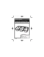
Fig 8. Dashboard switch loom

Dashboard switch loom connector


Dash switch

Summary of Contents for DL150LED

Page 1: ...1 USER INSTRUCTIONS with positioning light functions TRIPLE SWITCHING HIGH POWERED HARNESS FOR GENESIS AND VENOM LED LIGHTS ...

Page 2: ...mended Torque wrench recommended TOOL REQUIRED FOR NON STANDARD INSTALLATIONS Crimping tool PERSONAL SAFETY WARNING WARNING High intensity light source Do not look directly into the light during operation eye injury may result Visit lightforce com installations to view instructional videos NOTE If you are using a different switch with dash illumination not included a Lightforce Switch Adaptor not ...

Page 3: ...sitive ring terminal 5 Ignition pickup wire 6 Low beam pickup wire with bullet terminal positive 7 High beam pickup wire with bullet terminal negative 8 High beam pickup wire with bullet terminal positive 9 Dashboard switch loom connector 10 Dash illumination cable fitment optional 1 2 3 4 5 6 7 8 1 Yellow Dash Illumination from park lights 2 Black Negative 3 Blue Switch to Output to relay trigger...

Page 4: ... the insulated sleeved wires that run from the relay to the driving light connectors to each of your installed driving lights and connect the driving light connectors to the back of each light Ensure that cables do not touch the radiator or come in contact with any sharp edges 5 Secure all excess wire to the vehicle with cable ties supplied See Page 6 STEP 3 FULL INTENSITY MODE ONLY 1 Select the H...

Page 5: ...g a multi meter or test light locate the Low Beam positive wire located on the back of the headlight and fit the supplied T Tap over the Low Beam positive wire Figure 7 Two sizes of T Tap connectors are supplied in the kit the purple one suits small gauge wires 0 5 1 0mm2 the blue one is for heavy gauge wires 1 5 2 5mm2 For HB3 and all other configurations excluding H4 cut off the existing bullet ...

Page 6: ...ness must be aligned If you are using a different switch with dash illumination not included connect the dash illumination cable on the switch loom to your switch as directed by the user instructions for the switch STEP 6 CONNECT TO THE BATTERY 1 Connect the ring on the red wired battery connector to the positive battery terminal using a spanner 2 Connect the ring on the black wired battery connec...

Page 7: ...7 THIS PAGE IS INTENTIONALLY BLANK ...

Page 8: ...61 8 8346 0504 All logos and images are subject to relevant trademark and copyright protection Lightforce Pty Ltd Copyright 2019 Data and specifications contained maybe subject to change without notice Lightforce Australia Pty Ltd shall not be liable for damage malfunction failure resulting from accident misuse misapplication unauthorised repair neglect modification unauthorised or non standard re...

Reviews: