PROGRAMMING TIPS:
How
should
my
strange
drive
be
configured?
How
can
I
program
a
drive
if
it
doesn't
have
a
programming
plug?
-
A
great
temporary
programming
plug
can
be
a
dip
switch
with
the
proper
number of sections.
-
The
drive
number
may
begin
at
one
end or the other of the plug or row of
jumper
pins.
Leaving
the
other
pins
open,
short
one
end
or
the
other
and
start
the
computer.
If
the
light
flashes
as
the
computer
attempts
to
boot,
you
have
the
drive
select
pins
identified.
Odds
are,
the
first
four
pairs
of
pins
are
the
drive
select
sections
for
4
drives,
working
from
the outside toward the center.
-
After
finding
the
drive
select
pins,
attempt
to
program
the
drive
with
no
other
switches/pins
shorted.
If
an
error
develops,
short
a
pair
of
pins
and try again.
On the Computer Memories drive, the programming
is accomplished by pairs of pins and removable
jumper plugs. DS1 is the pair of pins closest to
the front of the drive, with DS2, DS3, and DS4,
in order, toward the rear of the drive.
I have no information on the remaining two pairs
of pins.
TERMINAL RESISTOR PACK:
Looking at the Miniscribe picture again, you can
also see the location of a Terminator Pack or
Terminal Resistor Pack. This resistor pack
serves the same purpose as on the floppy drives
and needs to be installed ONLY in the drive at
the end of the 34-conductor ribbon cable.
[ ] If this is your only hard drive, leave the
resistor pack installed. If this hard drive will
be an external drive, of a pair of hard drives,
install the resistor pack only on the last hard
drive on the 34-pin connector.
[ ] If the hard drive is replacing one of the
floppy drives, ensure the remaining floppy drive
has a terminal resistor pack and the drive
select is properly set, DS0 or DS1, as needed.
As with the floppy drives, it is the drive
select position on the programming plug that
determines the drive number or letter and it
doesn't matter if the first drive letter is
first or last on the cable. Therefore, drive 0
(E:) of a two drive system can be first or last
on the ribbon cable. It is always the last drive
on the ribbon cable that has the terminator
resistor installed.
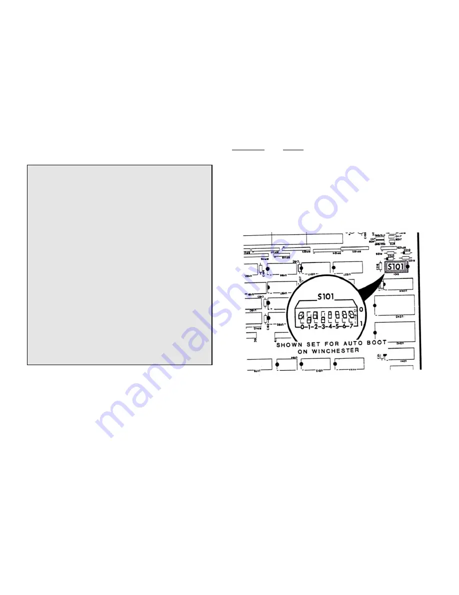
MOTHERBOARD DIP SWITCH:
After the initial testing and programming of the
hard drive, the computer can be set to auto boot
from the hard drive by changing the positions of
switch S101, Figure 3.
Note
: The positions 1 and 0 are not labeled on
all motherboards. The position 1 is always
toward the front of the computer, 0 is toward
the card cage.
Switch sections 0, 1, and 2 select the type of
drive that the system will boot from:
Section:
Device
0 1 2
Type:
0 0 0
5-1/4" Floppy Drive
1 0 0
8" Floppy Disk Drive
0 1 0
Winchester Hard Drive
1 1 0
SCSI/EEPROM Board
And Switch section 3 selects Auto or Manual
Boot, where:
1 = Auto boot
0 = Manual boot
Figure 3.
Switch S101 on the Motherboard
INSTALLING THE HARDWARE:
[ ] Both computer models require the Z-217
Winchester Controller Board be inserted in
any
free slot of the Card Cage at the rear of the
computer. See Figure 4. Note the position of the
large connector for the 4-pin power supply cable
on the left.
[ ] Installation of the hard drive in the All-
In-One Z-100 is shown in Figure 5. It involves
mounting the hard drive in the upper or lower
bay of the drive chassis, depending upon the
type of faceplate you have available.
If your hard drive has its own faceplate, you
may be able to cut a large opening in your
existing faceplate.
7


