background image


5

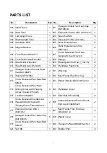
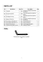
PARTS LIST


No. 

Description 

Qty No.

Description 

Qty

001  Main Frame 

1  021 

Hexagon Socket Pan Head Cap 
Bolt M8x40 

002  Base Tube 

1  022  Extension Sensor Wire (1000 mm)

003  Left Upright Tube 

1  023  Nylon Nut M8 

004  Right Upright Tube 

1  024  Sensor with Wire (210 mm) 

005  Handlebar Ø28 

1  025  Hand Pulse Sensor 

006  Magnet Bracket 

1  026 

Hand Pulse Sensor Wire 
(800 mm) 

007  Front Roller Ø42x417.5 

1  027 

Cross Recessed Pan Head 
Tapping Screw ST4.2x19 

008  Front Roller Axle Ø12x450 

1  028  Spring   

009  Rear Roller Ø60x444 

1  029  Rectangular End Cap (

30x15) 

010  Rear Roller Axle Ø12x496 

1  030  Handlebar Foam Grip 

011 

Hexagon Socket Cheese Head 
Cap Bolt M6x75 

2  031  Wire Clip 

012  Washer Ø13xØ6.2 

2  032  Main Frame Rear End Cap 

013 

Cross Recessed Pan Head Bolt
M6x20 

1  033  Plastic Washer Ø23.5xØ12.2x4 

014 

Cross Recessed Pan Head 
Drilling Screws with Tapping 
Screw Thread ST5.5x25 

6  034  Handlebar Cover 

015  Lock Knob M8x60 

1  035  Side Rail (975Lx30W) 

016 

Cross Recessed Countersunk 
Head Drilling Screws with 
Tapping Screw Thread M3x10 

2  036 

Incline Adjustment Frame Round 
End Cap Ø33xØ25x25 

017 

Extension Sensor Wire I   
(650 mm) 

1  037 

Main Frame Front End Cap 
(D50.8x41.4) 

018 

Hexagon Socket Pan Head Cap
Bolt M8x45 

5  038  Plastic Cover 

019 

Cross Recessed Pan Head Bolt
M5x15 

1  039  Transport Wheel Ø48xØ8.2x16.5 

020  Nut M6 

1  040  Rubber Pad 


Summary of Contents for 40160

Page 1: ... S MANUAL IMPORTANT Read all instructions carefully before using this product Retain this owner s manual for future reference The specifications of this product may vary from this photo and are subject to change without prior notice 2019 July ...

Page 2: ... INSTRUCTIONS 3 EXPLODED VIEW 4 PARTS LIST 5 TOOL 6 HARDWARE LIST 7 ASSEMBLY INSTRUCTIONS 8 OPERATING THE COMPUTER 15 STORAGE 16 MOVING THE TREADMILL 17 ADJUSTMENTS 18 LUBRICATION 22 MAINTENANCE 23 TROUBLESHOOTING 23 WARM UP AND COOL DOWN ROUTINE 24 ...

Page 3: ...r repairing free of charge any parts which may prove to be defective under normal home use This warranty does not include any damage caused by improper operation misuse or commercial application From the date of purchase the frame is warranted to be free from defects for 1 one year This warranty is offered only to the original owner and is not transferable Proof of purchase is required When orderi...

Page 4: ... Never wear loose clothing because it could run the risk of getting caught in the magnetic treadmill 8 Keep children and pets away from the equipment while in use 9 Do not use the magnetic treadmill outdoors This magnetic treadmill is for household use only 10 Only one person should be on the magnetic treadmill while in use 11 Keep the magnetic treadmill on a solid level surface with the minimum s...

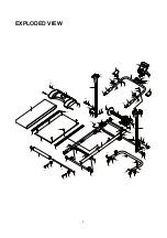
Page 5: ... 37 38 40 42 42 42 42 43 31 46 30 17 26 22 17 22 24 25 27 44 48 23 41 36 23 18 18 15 40 26 34 34 55 51 50 56 50 56 35 35 45 23 53 52 49 49 55 54 8 33 32 12 11 10 32 12 11 33 9 4 3 19 29 29 47 47 14 14 18 53 52 54 49 49 55 43 30 25 27 26 55 18 39 40 40 21 23 37 ...

Page 6: ... Ø12x496 1 030 Handlebar Foam Grip 2 011 Hexagon Socket Cheese Head Cap Bolt M6x75 2 031 Wire Clip 1 012 Washer Ø13xØ6 2 2 032 Main Frame Rear End Cap 2 013 Cross Recessed Pan Head Bolt M6x20 1 033 Plastic Washer Ø23 5xØ12 2x4 4 014 Cross Recessed Pan Head Drilling Screws with Tapping Screw Thread ST5 5x25 6 034 Handlebar Cover 2 015 Lock Knob M8x60 1 035 Side Rail 975Lx30W 2 016 Cross Recessed Co...

Page 7: ...nd Cap 2 051 Cross Recessed Pan Head Bolt M5x10 2 044 Magnet 39 5x25x12 6 052 Hexagon Socket Pan Head Cap Bolt M8x50 2 045 Running Deck 975x450x12T 1 053 Washer Ø22xØ8 3 2 046 Running Belt 2360x335x1 2T 1 054 Washer Ø16xØ8 3 4 047 Tension Control Knob 1 055 Curve Washer Ø16xØ8 3 4 048 Incline Adjuster Ø25x1 5Tx555 1 056 Washer Ø13xØ6 1 4 TOOL S5 Allen Wrench with Phillips Screwdriver 1 PC ...

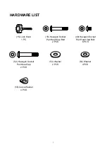
Page 8: ...ARDWARE LIST 15 Lock Knob 1 PC 18 Hexagon Socket Pan Head Cap Bolt 2 PCS 49 Hexagon Socket Pan Head Cap Bolt 6 PCS 52 Hexagon Socket Pan Head Cap 2 PCS 53 Washer 2 PCS 54 Washer 4 PCS 55 Curve Washer 4 PCS ...

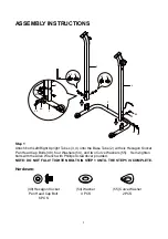
Page 9: ...Bolts 49 four Washers 54 and two Curve Washers 55 Semi tighten bolts with the Allen Wrench with Phillips Screwdriver provided NOTE DO NOT FULLY TIGHTEN BOLTS IN STEP 1 UNTIL THE STEP 5 IS COMPLETE Hardware 49 Hexagon Socket Pan Head Cap Bolt 6 PCS 54 Washer 4 PCS 55 Curve Washer 2 PCS 49 54 2 49 55 49 55 54 49 2 4 3 3 49 54 49 55 ...

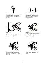
Page 10: ...nsion Control Knob 47 47 4 1 6 Step 2 3 Insert the resistance cable of the Tension Control Knob 47 to the Magnet Bracket 6 A 1 6 47 Step 2 4 Put the A cable end of resistance cable into the cable lock of Magnet Bracket 6 1 6 A C B Step 2 5 Pull the resistance cable down and force C into the slot of metal bracket 1 6 A C B Step 2 6 Finally tighten the B Nut by hand ...

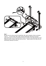
Page 11: ...e bolts with the Allen Wrench with Phillips Screwdriver provided Attach the Plastic Cover 38 onto the Main Frame 1 with four Cross Recessed Pan Head Bolts 50 and four Washers 56 that were removed Tighten bolts with the Allen Wrench with Phillips Screwdriver provided 38 50 56 50 56 2 1 50 56 1 38 1 50 56 ...

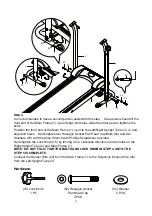
Page 12: ...Cap Bolts 52 and two Washers 53 with the Allen Wrench with Phillips Screwdriver provided Semi tighten the Lock Knob 15 by turning it in a clockwise direction into the holes on the Right Upright Tube 4 and Main Frame 1 NOTE DO NOT FULLY TIGHTEN BOLTS AND LOCK KNOB IN STEP 4 UNTIL THE STEP 5 IS COMPLETE Connect the Sensor Wire 24 from the Main Frame 1 to the Extension Sensor Wire 22 from the Left Up...

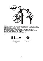
Page 13: ...ts with the Allen Wrench with Phillips Screwdriver provided NOW PLEASE FULLY TIGHTEN ALL BOLTS AND LOCK KNOB INSTALLED IN STEP 1 AND STEP 4 WITH THE ALLEN WRENCH WITH PHILLIPS SCREWDRIVER PROVIDED Install two Handlebar Covers 34 onto the Handlebar 5 Hardware 18 Hexagon Socket Pan Head Cap Bolt 2 PCS 55 Curve Washer 2 PCS 34 5 34 18 55 18 55 5 3 4 3 34 55 18 ...

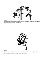
Page 14: ...from the Left Upright Tube 3 to the Extension Sensor Wire I 17 from the Handlebar 5 Step 7 Remove two Cross Recessed Pan Head Bolts 51 from the Computer 41 Remove bolts with the Allen Wrench with Phillips Screwdriver provided 17 22 3 4 22 17 5 51 41 ...

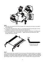
Page 15: ...ar 5 with two Cross Recessed Pan Head Bolts 51 that were removed Tighten bolts with the Allen Wrench with Phillips Screwdriver provided Step 9 The running belt has been adjusted to the running deck at the factory before it was shipped At times the running belt may get slippery during shipment After the treadmill is completely assembled use the Allen Wrench with Phillips Screwdriver provided to tur...

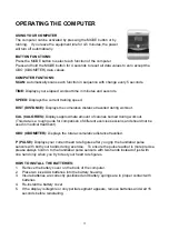
Page 16: ...ories burned during workout This data is a rough guide for comparison of different exercise sessions and should not be used in medical treatment ODO ODOMETER Displays the total accumulative distance travelled P PULSE Displays your current heart rate figures after you grip the handlebar pulse sensors with both your hands during exercise To ensure the pulse readout is more precise please always hold...

Page 17: ...h the Lock Knob may cause the treadmill accidental fall and cause bodily injury WARNING Do not stand under the deck when setting down the treadmill To prevent injury please make sure you have a firm hold when lifting up or setting down the main frame Do not undo the lock knob unless you have a firm hold and control of the treadmill base or it can drop to the ground quickly and dangerously when the...

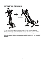
Page 18: ...moving and storage With the treadmill in the folded locked position firmly grasp the both Handlebars with both hands Next carefully tilt the treadmill back until it rolls freely on the transport wheels CAUTION Do not attempt to move the treadmill while it is in the unfolded position Handlebar ...

Page 19: ...a counterclockwise direction Adjusting the Incline Adjuster There are three incline angles that the Incline Adjuster can be set to Place one hand on the rear end of the main frame then lift the rear end of the main frame up and use your other hand to adjust the Incline Adjuster to the desired position Tension Control Knob Incline Angle 1 Incline Adjuster Incline Angle 2 Incline Angle 3 ...

Page 20: ...w Once after adjusting the Bolt 13 you also have to check if the tension wire is too loose if necessary you just adjust the B Nut 1 6 A C B 13 6 7 6 7 13 6 7 6 7 To decrease the tension turn the Bolt 13 in a clockwise direction To increase the tension turn the Bolt 13 in a counterclockwise direction ...

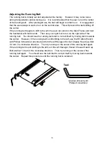
Page 21: ... right side of the running belt You should see the running belt start to correct itself by moving back towards the center However if the running belt is still shifting to the left use the S5 Allen Wrench with Phillips Screwdriver provided and turn the left Hexagon Socket Cheese Head Cap Bolt 1 2 turn in a clockwise direction Then try running on the center of the running belt again If the running b...

Page 22: ...e running belt again If the running belt is still shifting to the right turn the right Hexagon Socket Cheese Head Cap Bolt another 1 4 turn in the clockwise direction Then try running on the center of the running belt again You should see the belt start to correct itself by moving back towards the center Repeat this procedure until the running belt is centered If the running belt is slipping durin...

Page 23: ...ing belt and feel the top surface of the running deck If the surface is slick to the touch then no further lubrication is required If the surface is dry to the touch apply some lubricant How to apply lubricant Lift one side of running belt Pour some lubricant under the centre of the running belt on the top surface of the running deck Run on the treadmill for 3 to 5 minutes to evenly distribute lub...

Page 24: ...t come from the computer console are properly connected to the wires that come from the handlebar SOLUTION Check the batteries are correctly positioned and battery springs are in proper contact with batteries SOLUTION The batteries in the computer console may be dead Replace with new batteries PROBLEM There is no heart rate reading or heart rate reading is erratic inconsistent SOLUTION Make sure t...

Page 25: ... state at the end of each exercise session A proper cool down slowly lowers your heart rate and allows blood to return to the heart HEAD ROLLS Rotate your head to the right for one count you should feel a stretching sensation up the left side of your neck Then rotate your head back for one count stretching your chin to the ceiling and letting your mouth open Rotate your head to the left for one co...

Page 26: ...Lean against a wall with your left leg in front of the right and your arms forward Keep your right leg straight and the left foot on the floor then bend the left leg and lean forward by moving your hips toward the wall Hold then repeat on the other side for 15 counts TOE TOUCHES Slowly bend forward from your waist letting your back and shoulders relax as you stretch toward your toes Reach as far a...

Reviews: