background image

Introduction to STS2 Operations

59

8.2.4 Bypass

The static transfer switch can be manually bypassed to allow the power from a source to directly flow 

to the output load. This bypass allows the unit’s electronics to be serviced without dangerous voltages 

being present.
The STS2 includes key-interlocked maintenance bypass breakers that allow either input source’s elec-

tronics to be bypassed for maintenance without interruption of power to the load. The maintenance 

bypass allows all electronics to be isolated from the input, output, and bypass connections. Bypass 

instructions are available from the touch screen and are discussed later in this manual.

8.3

Operator Controls

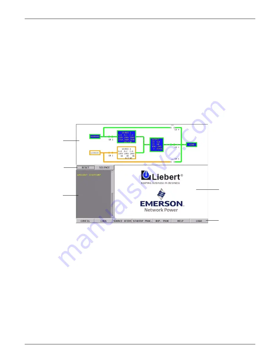
The STS2 is equipped with an interface to configure and monitor the unit either locally or remotely. 

The Color Graphical Display is a touch screen LCD that provides a color diagram (Mimic) that dis-

plays the current status of the unit. System parameters are displayed and help is available to define 

events. See 

Figure 45

 below and 

Figure 31

. The touch screen menus allow the operator to initiate 

source transfers, view event and history logs, and view bypass and other operational instructions. 

Figure 45 STS2 touch screen display

Touch screen control buttons allow you to reset alarms, silence the audible alarm, review configura-

tions, event and history logs, preferred source, startup and bypass procedures, and the help menu. 

Qualified personnel, with a password, can use these menus to configure parameters, select a pre-

ferred source, and do manual source transfers.
LED display units do not have the color LCD display. Instead of the touch screen, these units are 

monitored by a series of LEDs and controlled by a series of push buttons.
Both units can be accessed from a terminal, or a PC running terminal emulation software, that is 

attached to the unit. Through the RS-232 access, you can monitor and configure the unit, plus 

remotely select a preferred source. See 

12.1 - Using the RS-232 Port

on page 76 for instructions on 

using the RS-232 interface.

Mimic

Event Display

Event controls

Display Panel 

and 

Help Screen

Menu Options

Summary of Contents for POWER PROTECTION STATIC TRANSFER SWITCH

Page 1: ...POWER PROTECTION STATIC TRANSFER SWITCH 2 USER MANUAL 100 1000 Amp 50 60 Hz...

Page 2: ......

Page 3: ...Static Switch Without Anchoring 8 4 3 Leveling and Anchoring the Static Switch Using Floor Stand 8 5 0 POWER AND CONTROL WIRING 9 5 1 Input And Output Power Connections 9 5 2 Input Junction Box Insta...

Page 4: ...Automatic Transfer Retransfer 60 9 1 4 Emergency Transfer 61 9 1 5 Load Current Transfer Inhibit 61 9 1 6 SCR Failure 61 9 1 7 On Off Sequence 61 9 2 Detailed Component Description 61 9 2 1 Controls 6...

Page 5: ...13 3 Mimic Display 88 13 4 Event Controls 88 13 5 Event Display 88 13 6 Menu bar 88 13 6 1 Configuration Menu 88 13 6 2 Logs 101 13 6 3 Source Transfers 102 13 6 4 Startup Procedure 102 13 6 5 Bypass...

Page 6: ...5 2 3 Cooling 112 15 2 4 Access 113 15 2 5 Circuit Breakers 113 15 2 6 Cable Entrance 113 15 2 7 Doors 113 15 2 8 Color Graphical Display or LED Display 113 15 2 9 RS 232 Port 114 15 2 10 Terminal Por...

Page 7: ...l connection location diagram 800 1000 amp STS2 34 Figure 23 Control wiring for remote source selection option 35 Figure 24 Control wiring for the programmable relay board option 36 Figure 25 Control...

Page 8: ...unction box terminal wire size range 10 Table 6 Remote source selection terminal block 12 Table 7 Terminal block 1 and terminal block 2 wire connections 12 Table 8 Programmable relay board pinout 13 T...

Page 9: ...and install the unit in an area free from flammable liquids gases or corrosive substances The unit is designed to operate from solidly grounded AC power sources only Provide input over current protect...

Page 10: ...r should that be required 5 0 Power and Control Wiring provides instructions wiring the STS2 for power and control con nections 6 0 Options lists the options available for the STS2 7 0 Installation Dr...

Page 11: ...Three types of messages are used throughout this manual to stress important text Carefully read the information below each Warning Caution and Note and use professional skills and prudent care when pe...

Page 12: ...to verify that the model numbers correspond with the one specified Record the model numbers and serial numbers in the front of this installation manual A record of this information is necessary shoul...

Page 13: ...ocks from under the frame of the unit 4 Use a forklift to raise the unit off the pallet and onto the floor Ensure that the forklift is clear of the unit s casters and leveling feet Lift the unit from...

Page 14: ...switch see Figures 8 through 10 for location of that switch 3 1 Recommended Minimum Service Clearances The recommended service clearances are at the front of the unit The minimum service clearance req...

Page 15: ...tion at altitudes above 4000 feet 1200 m Figure 2 Maximum ambient temperature for full load operation at higher altitudes Table 2 Altitude conversion feet to meters Feet Meters Feet Meters Altitude 40...

Page 16: ...sters and leveling feet After final positioning of the unit adjust the leveling feet located in each corner of the frame base to level and stabilize the unit 4 3 Leveling and Anchoring the Static Swit...

Page 17: ...to the bus bars pro vided inside the unit These bus bars are accessible through the front of the unit Output power connections also are made to the bus bars provided inside the unit These bus bars ar...

Page 18: ...hipped in advance to be installed during the rough in stage of construction Locate the junction boxes a maximum of 8 feet 2 4 meters from the planned location of the Static Switch Due to a lack of cle...

Page 19: ...trals of two grounded power sources together effectively grounds each of the sources at more than one point which allows neutral current to flow on the ground system defeats ground fault protection cr...

Page 20: ...Connections are made to four of the connections using Form A dry contacts The con tacts are numbered left to right See 10 3 Enabling Remote Source Selection for instructions on enabling the Remote So...

Page 21: ...ary of an isolation transformer opti mized transfer greatly reduces the transformer magnetization current during automatic transfers through a new transfer control algorithm The Liebert algorithm pate...

Page 22: ...nication up to 1000 meters 3281 feet Information available from the RS 422 port includes the present switch status informa tion all monitoring parameters and all active alarms The Comms Board is equip...

Page 23: ...n dry contact allows the user to remotely select a source to be the preferred source in the same process as the local source transfer selection The unit s preferred source selection and Remote Source...

Page 24: ...on Box Installation Optional on page 10 for more information and specifi cations See Figure 30 for wiring details 6 13 Seismic Floor Anchors Seismic anchors are available for anchoring the unit to a c...

Page 25: ...XHAUST 3 INSTALLATION AND SERVICE ACCESS REQUIRED IN FRONT ONLY 4 HEAT OUTPUT 2710 BTU HR 0 80 KW HR MAX FOR 100A SWITCH 4680 BTU HR 1 37 KW HR MAX FOR 250A SWITCH 5 WEIGHT 780 LBS 354 KG 6 UNIT BOTTO...

Page 26: ...U HR 3 08 KW HR MAX FOR 600A SWITCH 5 WEIGHT 1200 LBS 544 KG 6 UNIT BOTTOM IS STRUCTURALLY ADEQUATE FOR FORKLIFT HANDLING 7 KEEP CABINET WITHIN 15 DEG OF VERTICAL WHILE HANDLING 8 COLOR IBM OFF WHITE...

Page 27: ...00 LBS 1134 KG 6 UNIT BOTTOM IS STRUCTURALLY ADEQUATE FOR FORKLIFT HANDLING 7 KEEP CABINET WITHIN 15 DEG OF VERTICAL WHILE HANDLING 8 COLOR IBM OFF WHITE 9 OPEN DOOR TO REPLACE AIR FILTER DISPOSABLE T...

Page 28: ...UTPUT 2710 BTU HR 0 80 KW HR MAX FOR 100A SWITCH 4680 BTU HR 1 37 KW HR MAX FOR 250A SWITCH 5 WEIGHT 780 LBS 354 KG 6 UNIT BOTTOM IS STRUCTURALLY ADEQUATE FOR FORKLIFT HANDLING 7 KEEP CABINET WITHIN 1...

Page 29: ...04 KW HR MAX FOR 400A SWITCH 10520 BTU HR 3 08 KW HR MAX FOR 600A SWITCH 5 WEIGHT 1200 LBS 544 KG 6 UNIT BOTTOM IS STRUCTURALLY ADEQUATE FOR FORKLIFT HANDLING 7 KEEP CABINET WITHIN 15 DEG OF VERTICAL...

Page 30: ...5 09 KW HR MAX FOR 1000A SWITCH 5 WEIGHT 2500 LBS 1134 KG 6 UNIT BOTTOM IS STRUCTURALLY ADEQUATE FOR FORKLIFT HANDLING 7 KEEP CABINET WITHIN 15 DEG OF VERTICAL WHILE HANDLING 8 COLOR IBM OFF WHITE 9...

Page 31: ...OOR BRACKETS ON FLOOR AT LEAST 75 FROM BACK WALL MARK LOCATION AND DRILL HOLES FIG 1 TO A MINIMUM DEPTH OF 4 12 INTO THE CONCRETE 3 INSTALL REAR CABINET BASE BRACKET FIG 2 TO EXISTING HOLES ON UNDERSI...

Page 32: ...FLOOR AT LEAST 75 FROM BACK WALL MARK LOCATION AND DRILL HOLES FIG 1 TO A MINIMUM DEPTH OF 4 12 INTO THE CONCRETE 3 INSTALL REAR CABINET BASE BRACKET FIG 2 TO EXISTING HOLES ON UNDERSIDE OF UNIT WITH...

Page 33: ...L MARK LOCATION A ND DRILL HOLES FIG 1 TO A MINIMUM DEPTH OF 4 12 INTO THE CONCRETE 3 INSTALL REAR CABINET BASE BRACKET FIG 2 TO EXISTING HOLES ON UNDERSIDE OF UNIT WITH TABS FACING BACK WALL USE SUPP...

Page 34: ...ORDANCE WITH NATIONAL 4 ALUMINUM AND COPPER CLAD ALUMINUM CABLES ARE 3 CONTROL WIRING AND POWER WIRING MUST BE RUN 2 TOP AND BOTTOM CABLE ENTRY AVAILABLE THROUGH AND LOCAL ELECTRICAL CODES NOT RECOMME...

Page 35: ...D ONE LINE DIAGRAM SYSTEM OUTPUT PS212101 Rev 3 NOT RECOMMENDED NOTES 1 ALL DIMENSIONS ARE IN INCHES AND MILLIMETERS 5 ALL WIRING IS TO BE IN ACCORDANCE WITH NATIONAL 4 ALUMINUM AND COPPER CLAD ALUMIN...

Page 36: ...CB3 K3 K1 K2 CB5 SOURCE 1 CB1 CB2 SOURCE 2 NOT RECOMMENDED NOTES 1 ALL DIMENSIONS ARE IN INCHES AND MILLIMETERS 5 ALL WIRING IS TO BE IN ACCORDANCE WITH NATIONAL 4 ALUMINUM AND COPPER CLAD ALUMINUM CA...

Page 37: ...K2 CB5 SOURCE 1 CB1 CB2 SOURCE 2 CB3A CB3 CB3A NOT RECOMMENDED NOTES 1 ALL DIMENSIONS ARE IN INCHES AND MILLIMETERS 5 ALL WIRING IS TO BE IN ACCORDANCE WITH NATIONAL 4 ALUMINUM AND COPPER CLAD ALUMIN...

Page 38: ...K1 CB5 K3 K1 K2 SOURCE 1 CB1 SOURCE 2 CB2 NOT RECOMMENDED NOTES 1 ALL DIMENSIONS ARE IN INCHES AND MILLIMETERS 5 ALL WIRING IS TO BE IN ACCORDANCE WITH NATIONAL 4 ALUMINUM AND COPPER CLAD ALUMINUM CA...

Page 39: ...RDANCE WITH NATIONAL 4 ALUMINUM AND COPPER CLAD ALUMINUM CABLES ARE 3 CONTROL WIRING AND POWER WIRING MUST BE RUN 2 TOP AND BOTTOM CABLE ENTRY AVAILABLE THROUGH AND LOCAL ELECTRICAL CODES RUN IN A SEP...

Page 40: ...R LESS THAN THE AMPERE RATING OF THE STATIC SWITCH MOLDED CASE BREAKER VOLTAGE STATIC TRANSFER SWITCH 2 MOLDED CASE BREAKER SCHEDULE 1000A 400A 100A 250A 600A 800A STS2 RATING AMPACITY VENDOR TYPE NSF...

Page 41: ...INPUT CONTACT ISOLATOR BOARD PROGRAMMABLE RELAY SEE OPTION OPTION LOCATION DETAIL LOCATION DETAIL BOARD OPTION SEE NOTE 2 OPTION OR PROGRAMMABLE RELAY EXTERNAL AND INTERNAL CARD NIC OPTION NETWORK INT...

Page 42: ...CE CARD NIC OPTION EXTERNAL AND INTERNAL COMMS BOARD FOR SITESCAN FRONT VIEW WITH FRONT DOOR REMOVED CONTROL WIRING PS213800 Rev 1 OPTION LOCATION DETAIL SELECT OPTION REMOTE SOURCE BOARD OPTION SEE N...

Page 43: ...DIAGRAM FOR LOCATION OF REMOTE SOURCE SELECTION OPT 4 REFER TO STATIC TRANSFER SWITCH CONTROL CONNECTION SEPARATE FROM POWER WIRING CONTROL WIRING RUNS 3 ALL CONTROL WIRING BY OTHERS MUST BE RUN SHOUL...

Page 44: ...TION OPERATION MAINTENANCE SIGNAL CHANNELS WITH 2 FORM C DRY CONTACTS PER 2 PROGRAMMABLE RELAY BOARD OPTION INCLUDES 8 TERMINAL BLOCKS 1 THROUGH 15 1 CUSTOMER CONTROL WIRING CONNECTION POINTS ARE AND...

Page 45: ...INED IN THE SAME CONDUIT MANUAL FOR CONFIGURING THE INPUT CONTACT ISOLATOR 3 REFER TO INSTALLATION OPERATION MAINTENANCE 2 CUSTOMER PROVIDED NORMALLY OPEN DRY CONTACTS 1 CUSTOMER CONTROL WIRING CONNEC...

Page 46: ...CORDANCE WITH NATIONAL OF STATIC TRANSFER SWITCH FOR LOCATION OF COMMS 5 REFER TO CONTROL CONNECTION LOCATION DIAGRAM SEPARATE FROM POWER WIRING CONTROL WIRING RUNS 4 ALL CONTROL WIRING BY OTHERS MUST...

Page 47: ...ECTION LOCATION DIAGRAM OF SEPARATE FROM POWER WIRING CONTROL WIRING RUNS 4 ALL CONTROL WIRING BY OTHERS MUST BE RUN SHOULD NOT BE COMBINED IN THE SAME CONDUIT 3 REFER TO INSTALLATION OPERATION MAINTE...

Page 48: ...COMBINED IN THE SAME CONDUIT MANUAL FOR CONFIGURING THE NETWORK INTERFACE 3 REFER TO INSTALLATION OPERATION MAINTENANCE 1 WIRE SIZE AND TYPE 10 100 BASE T ETHERNET CABLE WITH RJ45 PLUG CONNECTOR THE L...

Page 49: ...IEW UPPER HALF OF UNIT WITH DOOR OPENED LCD DISPLAY SEE DETAIL A PS213006 Rev 1 DETAIL A RXD DB9 CONNECTOR TXD GND NOTES 1 RS 232 COMMUNICATION THROUGH DB9 CONNECTOR 2 CONNECTOR ACCESSIBLE WITH FRONT...

Page 50: ...76 6 AWG TO 2 0 AWG WIRE SIZE RANGE RECOMMENDED LOCATION FOR CUSTOMER CONNECTION OF INPUT POWER RACEWAY BY OTHERS 3 PHASE 3 WIRE PLUS GROUND LOCATION OF FACTORY SUPPLIED INPUT POWER CABLE ASSEMBLY INP...

Page 51: ...E XFERS RESET SI SCR SHORT S2 SCR SHORT ALARM CONTROLS MIMIC CB 2 SILENCE ALTERNATE 30 SOURCE 2 A B B C C A 195V 195V 195V 0A 0A 0A 0 0 HZ CB 1 PREFERRED SOURCE 1 A B B C C A 208V 208V 208V 200A 200A...

Page 52: ...HBUTTON OUTPUT POWER IS PRESENT PUSHBUTTON TO SELECT SOURCE 2 AS THE PREFERED SOURCE SOURCE TRANSFER INHIBITED SOURCE 2 WITHIN TOLERANCE SOURCE 2 POWER IS PRESENT SOURCE 1 POWER IS PRESENT GREEN H YEL...

Page 53: ...R STAND FEET LOOSEN ADJUST AND TIGHTEN THE NUTS AND JAM NUT SHOWN IN FOOT DETAIL A B ON DWG PS215000 FLOOR STAND MUST BE LEVEL AND ALL FEET MUST BE TOUCHING THE FLOOR ATTACH FLOOR STAND FEET USING 1 2...

Page 54: ...12 1 75X40MM SPLIT LOCK WASHER M12 FLAT WASHER M12 SEE DETAIL C 2 PLACES CAP SCREW M12 1 75X40MM SPLIT LOCK WASHER M12 FLAT WASHER M12 REAR UPPER STS2 BRACKET REAR SIDE REAR LOWER BRACKET FIG 4 RIGHT...

Page 55: ...ACKET TABS TO SLIDE INTO LOWER REAR BRACKET SLOTS 2 PLACES CAP SCREW M10 1 5X30MM SPLIT LOCK WASHER M10 FLAT WASHER M10 2 PLACES CAP SCREW M12 1 75X40MM SPLIT LOCK WASHER M12 FLAT WASHER M12 LOWER FRO...

Page 56: ...Drawings 48 Figure 36 Installation drawing seismic floor stand 100 250A NOTE SEE DWGS PS215000 PS215001 AND PS215002 FOR DETAILS 30 0 77 0 32 1 RAISED FLOOR FRONT VIEW RIGHT SIDE VIEW ISOMETRIC VIEW P...

Page 57: ...CAL HEIGHT OF FLOOR STAND FEET LOOSEN ADJUST AND TIGHTEN THE NUTS AND JAM NUT SHOWN IN FOOT DETAIL A B ON DWG PS216000 FLOOR STAND MUST BE LEVEL AND ALL FEET MUST BE TOUCHING THE FLOOR ATTACH FLOOR ST...

Page 58: ...ET FRONT 2 PLACES CAP SCREW M12 1 75X40MM SPLIT LOCK WASHER M12 FLAT WASHER M12 SEE DETAIL C 2 PLACES CAP SCREW M12 1 75X40MM SPLIT LOCK WASHER M12 FLAT WASHER M12 REAR UPPER STS2 BRACKET REAR SIDE RE...

Page 59: ...ACKET TABS TO SLIDE INTO LOWER REAR BRACKET SLOTS 2 PLACES CAP SCREW M10 1 5X30MM SPLIT LOCK WASHER M10 FLAT WASHER M10 2 PLACES CAP SCREW M12 1 75X40MM SPLIT LOCK WASHER M12 FLAT WASHER M12 LOWER FRO...

Page 60: ...Drawings 52 Figure 40 Installation drawing seismic floor stand 400 600A NOTE SEE DWGS PS216000 PS216001 AND PS216002 FOR DETAILS 38 77 0 32 1 RAISED FLOOR FRONT VIEW RIGHT SIDE VIEW ISOMETRIC VIEW PS...

Page 61: ...ER FEET NUTS 4 FLOOR STAND CAN BE MOUNTED NEXT TO A WALL IF NEEDED REAR ACCESS NOT REQUIRED INSTALL FLOOR STAND WITH FEET ORIENTATED AS SHOWN IN BOTTOM VIEW DWG PS217000 TO ADJUST VERTICAL HEIGHT OF F...

Page 62: ...ET FRONT 2 PLACES CAP SCREW M12 1 75X40MM SPLIT LOCK WASHER M12 FLAT WASHER M12 SEE DETAIL C 2 PLACES CAP SCREW M12 1 75X40MM SPLIT LOCK WASHER M12 FLAT WASHER M12 REAR UPPER STS2 BRACKET REAR SIDE RE...

Page 63: ...LIDE INTO LOWER REAR BRACKET SLOTS 2 PLACES CAP SCREW M10 1 5X30MM SPLIT LOCK WASHER M10 FLAT WASHER M10 2 PLACES CAP SCREW M12 1 75X40MM SPLIT LOCK WASHER M12 FLAT WASHER M12 LOWER FRONT BRACKET NOTE...

Page 64: ...wings 56 Figure 44 Installation drawing seismic floor stand 800 1000A NOTE SEE DWGS PS217000 PS217001 AND PS217002 FOR DETAILS 84 77 0 32 1 RAISED FLOOR FRONT VIEW RIGHT SIDE VIEW ISOMETRIC VIEW 32 52...

Page 65: ...rent and environmental parameters can be configured to trigger events that can sound an alarm write to a history log and either transfer sources or inhibit a transfer In units not equipped with the to...

Page 66: ...l solid state power switching devices are rated to prevent hazardous device failure in power systems with avail able fault currents up to the defined limits as listed in 15 1 5 Electrical Requirements...

Page 67: ...elp is available to define events See Figure 45 below and Figure 31 The touch screen menus allow the operator to initiate source transfers view event and history logs and view bypass and other operati...

Page 68: ...anual transfer by selecting the inactive source as the preferred source On a manual transfer the STS2 transfers between the two sources with less than one 1 millisecond interruption of power to the lo...

Page 69: ...92 under the Source Set Points heading for details 9 1 6 SCR Failure The STS2 continuously monitors the status of the SCR switching devices for proper operation In the event of a shorted SCR on the i...

Page 70: ...aults and alarms are detected and displayed on the LCD See 11 0 Alarm and Faults on page 71 for more information on events A set of event masks can be configured through the LCD to trigger a system re...

Page 71: ...installed on the control board This alarm is triggered by an alarm condition detected on the unit The alarm can be turned off from the touch screen Color Graphical Display units or by a push button L...

Page 72: ...fers to the LCD touch screen display This display is discussed in more detail later in the manual See 13 0 STS2 Touch Screen Display See Figures 14 19 for circuit breaker locations CAUTION Before unit...

Page 73: ...rectly indicated on the Mimic screen 8 Verify that boxes for the preferred source and corresponding static transfer switch are highlighted on the Mimic screen indicating which side of the Static Trans...

Page 74: ...47 Transfer is inhibited if the deviation exceeds the parameter set in the Source Set Points See User Settings on page 89 If your system contains the LED front panel instead of the LCD touch screen r...

Page 75: ...ELECT choice If your system contains the LED display or you are configuring the system from the RS 232 port see 12 1 Using the RS 232 Port on page 76 for instructions on using the that interface 10 4...

Page 76: ...ontains the LED display see 14 2 3 Maintenance Bypass GREEN LEDS ON THE GATE DRIVER BOARD ARE VIEWABLE THROUGH THIS SLOT INDICATE THAT THE STS IS ON SOURCE 1 GREEN LEDS ON THE GATE DRIVER BOARD ARE VI...

Page 77: ...o remove power from static switch To return to the normal mode 1 Remove the key from CB5 and insert it in the CB1 breaker interlock 2 Rotate key to retract interlock 3 Close source input breaker CB1 4...

Page 78: ...r CB5 8 Rotate the keys in CB5 interlock to extend the interlock 9 Remove the proper key from CB5 interlock and insert it into CB1 breaker interlock 10 Rotate the key to retract the CB1 breaker interl...

Page 79: ...alarm messages remain active until the alarm condition has been corrected and the RESET button is pushed See 11 1 Event Mask for more information on latching When the system is furnished with an opti...

Page 80: ...ted major alarm occurs the History Status buffer is frozen capturing 64 sequential frames before and after the alarm condition When the History Status buffer is frozen a History Log is created Two His...

Page 81: ...s soon as the load current and source voltage return to nor mal and transfers are no longer inhibited In manual mode the alarm remains active and transfers are inhibited until the conditions return to...

Page 82: ...scription Cause Action 001 S1 SCR SHORT One or more of the SCRs for Source 1 have shorted and failed D F A E 002 S2 SCR SHORT One or more of the SCRs for Source 2 have shorted and failed D F A E 003 S...

Page 83: ...Output circuit breaker CB3 is open A E 089 CB3A OUTPUT OPEN Output circuit breaker CB3A is open A E 090 S1 PHASE ROT ERROR Source 1 phase rotation error A E 091 S2 PHASE ROT ERROR Source 2 phase rota...

Page 84: ...k Interface Card NIC optional the NIC provides connectivity to any TCP IP based Ethernet network to allow the device to communicate with network management systems NMS via SNMP Events can be transmitt...

Page 85: ...t the commands Some terminal commands require a password to function Use the PWD command and a valid pass word to gain access Table 10 Terminal Commands Keys Function Displays this help menu or specif...

Page 86: ...iguration For example Event Masks are group 4 and Sys tem Settings are group 2 The numbers shown below are entered for the group parameter For exam ple start of a System Settings command is SPT 2 The...

Page 87: ...large amount of data within a single entry A detailed description of this type appears in section 12 1 3 Setting Bitpacked Options with the Terminal on page 81 Event Masks This type is a specially for...

Page 88: ...ndervoltage Detect Delay Integer In number of lines cycles 10 SRC2 Overvoltage Setpoint Integer In of nominal above nominal 11 SRC2 Overvoltage Detect Delay Integer In 1 4 lines cycles 12 SRC2 I peak...

Page 89: ...and features are as follows Options_1 bit0 HasDualOutputBreaker bit1 HasPDU bit2 Has4PoleTransferSwitch bit3 HasShuntTrip bit4 HasWyeOutputXfmr bit5 HasExternalPrecisionTimeSource bit6 HasSFA bit7 Ha...

Page 90: ...value for that group For example if the fourth bit in a group is set to 1 the group group s binary value is 0001 Each group is translated into a hexidecimal equivalent The group with the value of 000...

Page 91: ...n means that mask is disabled Refer to 11 1 Event Mask on page 71 for more information on event masks and their associated flags Unlike the System and User Settings mask values are set by designated l...

Page 92: ...nd go into the Event Log use SPT 4 12 D E To disable all masks for event 120 INPUT CONTACT 1 use SPT 4 120 D L S E A To breakdown this syntax for the last example SPT SVT command 4 group parameter ide...

Page 93: ...otification and other system setpoints The touch screen also provides buttons to reset alarms and turn off audible alarms such as a horn 13 1 Display Overview The STS2 Color Graphical Display provides...

Page 94: ...actory to default settings These settings enable the unit to be brought up without the need to enter all selectable parameters The menus allow the set tings to be customized Figure 50 Menus Figure 51...

Page 95: ...location of the key lockout switch To disable the changes turn the key to the top of the switch toward the closed padlock To enable changes turn the key to the horizontal position toward the open padl...

Page 96: ...message in the Event Display to display more information in the Display Panel to the left The selected status is displayed in bold type 13 6 Menu bar As previously mentioned the menu bar provides both...

Page 97: ...to disable the setting 3 Select SAVE to keep the settings Figure 53 Event mask dialog box User Settings The User Settings choice allows you to adjust the user accessible switch settings Access is limi...

Page 98: ...t percentage of the nominal voltage the STS2 transfers from the current source to the opposite source Slow UV Setting if the voltage remains this set percentage below the nominal voltage for the perio...

Page 99: ...rence between the sources and applies to all manual transfers as well as any auto retransfer a Configure this setting with a range of 1 30 degrees The default setting is 15 degrees and the resolution...

Page 100: ...User Settings dialog box You can select TEST to briefly sound the alarm to judge its volume 11 Select DISPLAY BRIGHTNESS A dialog box is displayed with HI and LO settings This choice sets the brightn...

Page 101: ...ns dialog box allows you to configure the communications settings for the STS2 Select COMM OPTIONS from the System Settings Menu The Comm Options dialog box is displayed See Figure 56 An option can be...

Page 102: ...e Upon successful connection the system transmits a present status data including all active alarms messages After transmission the modem automatically hangs up and returns to the auto answer mode To...

Page 103: ...ect NO to deactivate the dial out feature 14 Select SAVE to keep the modem configuration settings 15 Select YES in the Comm Options dialog box to activate the settings You are returned to the Comm Opt...

Page 104: ...e a fan problem could be indicated by naming the button FAN 4 Select OK on the keyboard to keep your label 5 Select DELAY A keypad is displayed prompting you for a delay time in seconds for a conditio...

Page 105: ...ing is selected for a relay no other event needs to be assigned for that relay ON SOURCE 1 or ON SOURCE 2 can be assigned to a relay to send a notification when that source is being used by the load O...

Page 106: ...do so you should group the events logically to simplify troubleshooting when an event is triggered 4 Select SAVE to keep the settings 5 Select OK for the applicable Programmable Options Board option i...

Page 107: ...gs that you want activated 2 Select SAVE to keep the settings Whenever you make modifications to the any of the Comm Options select SAVE to keep the changes System Options Most System Options are conf...

Page 108: ...sformer choice in the System Options dialog box Remote Source Selection If your system is configured with the optional Remote Source Selection it must be enabled from the System Options menu See 5 5 R...

Page 109: ...LOGS from the menu bar to open the Logs menu 2 Select EVENT LOG from the menu 3 Use the UP and DOWN buttons to scroll through the event list 4 Select OK to close the Event Log The data remains in the...

Page 110: ...provided on 10 1 Normal System Turn On for Color Graphical display units and 14 2 1 Normal System Turn On for LED Display units 13 6 5 Bypass Procedure You can access instructions for bypassing the st...

Page 111: ...Color Graphical Display touch screen See 12 1 Using the RS 232 Port for instructions on setting up and using a terminal with the unit 14 1 LEDs and Buttons and Key Lockout Switch The LED Display unit...

Page 112: ...green LED is lit if the button has been pushed to set Source 1 as the preferred source I Green Push button to select Source 2 as the preferred source A green LED is lit if the button has been pushed...

Page 113: ...your STS2 The LEDs provide the basic information required to ensure proper operation To monitor metering data use a PC terminal 1 Ensure that all STS2 breakers CB1 CB2 CB3A if supplied CB3 CB4 and CB...

Page 114: ...Set Points To manually select the preferred source 1 Ensure that the Transfer Inhibit NOXF LED is not lit If the Transfer Inhibit LED is lit Check to see if the red alarm LED is lit If the alarm LED i...

Page 115: ...y into the CB4 bypass breaker interlock 6 Rotate interlock keys in the CB4 bypass breaker interlock to retract the interlock 7 Close bypass breaker CB4 The LED for CB4 turns on 8 Open source input bre...

Page 116: ...to remove power from static switch The LEDs for CB3 and CB3A if supplied turn off 10 Verify that the output LED is lit Power is now flowing directly from the source to the load without passing through...

Page 117: ...nt output configuration The LEDs for CB3 and CB3A if supplied and the output OUT are turned off 3 Open the input switches CB1 and CB2 The LEDs for CB1 and CB2 are turned off 4 To completely de energiz...

Page 118: ...4 wire plus ground The STS2 is designed to accept an input neutral from each source The neutral is switched in the 4 pole static transfer switch only The voltage shall be within 10 of the nominal volt...

Page 119: ...time is less than 4 ms The over voltage detection uses a single threshold with programmable level and delay time See User Settings on page 89 for instructions on configuring these settings 15 1 8 Envi...

Page 120: ...allation plus permanent leveling feet for final installation The unit also can be fastened to the floor using optional seismic anchors to meet seismic Zone 4 requirements See 4 0 Locating the STS2 and...

Page 121: ...to prevent improper maintenance bypassing of the solid state switch A bypass breaker cannot be closed unless the solid state switch is connected to the same input source and only one bypass breaker ca...

Page 122: ...ated non SELV and ESD protected to 15kV air discharge The connector is a 6 Pin MTA plug with connections shown below A DB9 male connector is added and connected parallel to the 6 position header It is...

Page 123: ...t and 14 2 3 Maintenance Bypass on page 107 for instructions using the LED units 15 2 13Fuseless Design All STS2 units are fuseless and are UL rated for use with upstream circuit breakers only 15 2 14...

Page 124: ...Source 2 has shorted Transferring between sources has been inhibited Press SILENCE on the touch screen to turn off the audible alarm if so configured If you are accessing the STS2 system from a termi...

Page 125: ...itored Contact Liebert for technical support at 1 800 LIEBERT 800 543 2378 Press SILENCE on the touch screen to turn off the audible alarm if so configured If you are accessing the STS2 system from a...

Page 126: ...m if so configured If you are accessing the STS2 system from a terminal type SH and press RETURN on your keyboard to turn off the audible alarm This event was written to the Event Log if so configured...

Page 127: ...0 543 2378 Press SILENCE on the touch screen to turn off the audible alarm if so configured If you are accessing the STS2 system from a terminal type SH and press RETURN on your keyboard to turn off t...

Page 128: ...accessing the STS2 system from a terminal type SH and press RETURN on your keyboard to turn off the audible alarm Contact Liebert for technical support at 1 800 LIEBERT 800 543 2378 This event was wr...

Page 129: ...y If you are accessing the STS2 system from a terminal type CA and press RETURN on your keyboard S2 CURR SENSE FAIL Source 2 Current Sense Failure The module monitoring the current from Source 2 has f...

Page 130: ...o configured If you are accessing the STS2 system from a terminal type SH and press RETURN on your keyboard to turn off the audible alarm Contact Liebert for technical support at 1 800 LIEBERT 800 543...

Page 131: ...he audible alarm if so configured If you are accessing the STS2 system from a terminal type SH and press RETURN on your keyboard to turn off the audible alarm Contact Liebert for technical support at...

Page 132: ...e alarm if so configured If you are accessing the STS2 system from a terminal type SH and press RETURN on your keyboard to turn off the audible alarm The alarm is latched and must be reset after the v...

Page 133: ...off the audible alarm if so configured If you are accessing the STS2 system from a terminal type SH and press RETURN on your keyboard to turn off the audible alarm This event has been written to the...

Page 134: ...lay set points configured under the User Settings An S2 Fail alarm was also issued and source transfer has been inhibited The load of the STS2 has been transferred to Source 1 Press SILENCE on the tou...

Page 135: ...SILENCE on the touch screen to turn off the audible alarm if so configured If you are accessing the STS2 system from a terminal type SH and press RETURN on your keyboard to turn off the audible alarm...

Page 136: ...rm if so configured If you are accessing the STS2 system from a terminal type SH and press RETURN on your keyboard to turn off the audible alarm This event and the system status surrounding it have be...

Page 137: ...s from the preferred source to the alternate source in the last five minutes As a result automatic retransfers back to the preferred source is now disabled To clear this alarm condition assign the alt...

Page 138: ...e display If you are accessing the unit from a terminal type CA and press RETURN on your keyboard CB5 S1 BYP CLOSED Circuit Breaker 5 Source 2 Bypass Breaker Closed Circuit breaker 5 is not open The i...

Page 139: ...the touch screen to turn off the audible alarm if so configured If you are accessing the STS2 system from a terminal type SH and press RETURN on your keyboard to turn off the audible alarm This event...

Page 140: ...the History Logs were not already full This event was also written to the Event Log if so configured Press SILENCE on the touch screen to turn off the audible alarm if so configured If you are access...

Page 141: ...ress RESET on the display If you are accessing the unit from a terminal type CA and press RETURN on your keyboard INPUT CONTACT 4 Input Contact Isolator 4 Occurrence of the indicated external event ha...

Page 142: ...ble alarm if so configured If you are accessing the STS2 system from a terminal type SH and press RETURN on your keyboard to turn off the audible alarm The event with its assigned name was written to...

Page 143: ...arm press RESET on the display If you are accessing the unit from a terminal type CA and press RETURN on your keyboard TIME REPROGRAMMED System Time Reprogrammed The system s time setting has been upd...

Page 144: ...inal type CA and press RETURN on your keyboard HIST LOGS FULL History Logs Full The history buffer has reached its capacity for both history logs No further history logs can be written until the logs...

Page 145: ...eferred Source Selection on page 66 For an LED equipped unit see 14 2 2 Manual Transfer Preferred Source Selection on page 106 17 3 Changing the Air Filter A standard furnace filter is installed behin...

Page 146: ...maintenance plans and service contracts For repair or maintenance service outside the 48 contiguous states contact Liebert Global Services if available in your area For areas not covered by Liebert G...

Page 147: ...l device Up to ten 10 events can be programmed to each channel See 6 1 Programmable Relay Board for more information on the PRB If your STS2 has the PRB option installed list the settings below for fu...

Page 148: ...Maintenance 140 Channel 8 Channel 9 Channel 10 PRB Notes...

Page 149: ...inputs to be routed through the static transfer switch s alarm network See 6 4 Input Contact Isolator Board for more information on the ICI If your STS2 has the ICI option installed list the settings...

Page 150: ...Maintenance 142...

Page 151: ......

Page 152: ...liability for damages resulting from use of this information or for any errors or omissions 2005 Liebert Corporation All rights reserved throughout the world Specifications subject to change without n...

Reviews: