LG W3S1 Series Service Manual Download Page 24

- 24 -

1

2

Blue Wire

Black Wire

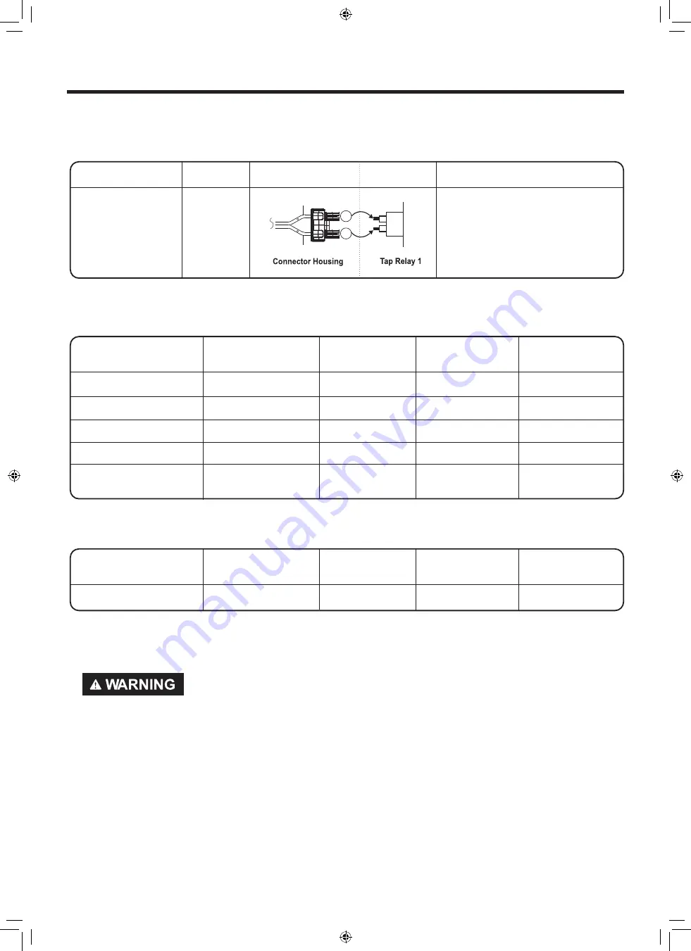
< Table 2 > : Connection of Tap Relay with PCB ASSEMBLY (Gas)

< Table2 > : Incorrect connection of the tap relay and connector housing (Gas)

Color

Harness

PCB

Remark

Connector Housing

Black

Check the matching color between
harness wire and tap relay.
(Black housing – black tap relay)

3.  Status Mode Of Wrong Connection

< Table1 > : Incorrect connection of the tap relay and connector housing (Electric)

Items

Case

Heater1

Operation(black)

Heater2

operation(White)

PCB condition

of operation

1.Black and White Housing

Wire 

 CROSS

Off

Off

Power Off

2.Black Housing

Wire 

 CROSS

Off

Off

Power Off

3.White Housing

Wire 

 CROSS

Normal

Normal

Power Off

*4.Black and White Housing

Housing CROSS

Heater 2

Heater 1

Power Off

5.Black and White Housing

Housing and Wire 

CROSS

Off

Off

Power Off

Items

Case

Heater1

Operation(black)

Heater2

operation(White)

PCB condition

of operation

1. Black and white housing

Wire 

 CROSS

Off

Off

Power Off

CAUTION! Improper connection of the heater can damage the heater or the main board.

Summary of Contents for W3S1 Series

Page 1: ...onic means publication modification copying or transmission of this Service Manual is STRICTLY PROHIBITED unless you have obtained the prior written consent of the LG Electronics entity from which you received this Service Manual The material covered by this prohibition includes without limitation any text graphics or logos in this Service Manual Copyright 2019 2021 LG Electronics Inc All rights r...

Page 2: ...cal appliance Do not touch any electrical switches Do not use any phone in your building Clear the room building or area of all occupants Immediately call your gas supplier from a neighbor s phone Follow the gas supplier s instructions carefully If you cannot reach your gas supplier call the fire department IMPORTANT Electrostatic Discharge ESD Sensitive Electronics ESD problems are present everyw...

Page 3: ... 7 1 Safety Caution 35 7 2 Error Mode Summary 35 7 3 Troubleshooting With Error Washer 38 7 4 Troubleshooting Else Washer 42 7 4 Troubleshooting Else Dryer 47 7 5 Troubleshooting Not Drying Dryer 54 7 6 Troubleshooting for flow sensor dryer 74 7 7 Before using the Tag On function 75 8 COMPONENT TESTING informat WASHER 79 8 1 Filter Assembly Line Filter 79 8 2 Door Lock Switch Assembly 80 8 3 Stato...

Page 4: ...with door open Capacity Washer 4 5 cu ft DOE Dryer Steam cycle IEC 7 4 cu ft 8 lb 3 6 kg Normal cycle IEC 7 4 cu ft 22 5 lb 10 2 kg Weight Gas 314 3 lb 142 6kg 327 1 lb 148 4 kg Electric 311 6 lb 141 3 kg 323 7 lb 146 8 kg To reduce the risk of injury you must adhere to all industry recommended safety procedures including the use of long sleeved gloves and safety glasses Failure to follow all of t...

Page 5: ...change the settings during operation SMART DIAGNOSIS Should yo u experience any technical diffic ulty with your washing machine is capable of producing multiple distinct different motions for optimal washing performance with very little noise and vibration The motor assembly also contains fewer moving parts thus resulting in fewer repairs How to USE Press and hold the Steam Extra Rinse Washer Stea...

Page 6: ...el the washing program then proceeds Spinning does not proceed until the water in the tub drains to a certain level The door can be opened by pulling the door handle whenever washer is not in operation When the cycle is completed the DOOR LOCKED light will turn off If a power failure has occurred while in operation the door will unlock after 5 minutes Clicking sounds can be heard when the door is ...

Page 7: ...Dry Dryer for 3 seconds to either lock or unlock the machine s controls Only the Power button remains active while the Control Lock feature is engaged The Control Lock can be activated while the machine is already in operation The Control Lock will remain engaged until the end of the current cycle To disengage the Control Lock press and hold Soil Washer Time Dry Dryer for 3 seconds The FlowSenseTM...

Page 8: ...r Washer Drum Washer Door Magnet Drain Hose Drain Pump Filter Drain Pump Filter Cover Leveling Feet Power Cord for Dryer gas models Terminal Block Access Panel for electric models Cold Water Inlet for Dryer System Exhaust Duct Outlet Gas connection for gas models Hot and Cold Water Inlets Shipping Bolts Drain Hose Power Cord for washer ...

Page 9: ...rough LG Website US www lg com us NOTE Contact LG Customer Service at 1 800 243 0000 1 888 542 2623 in Canada if any accessories are missing For your safety and for extended product life use only authorized components The manufacturer is not responsible for product malfunction or accidents caused by the use of separately purchased unauthorized components or parts The images in guide may be differe...

Page 10: ...iance to see whether it functions correctly STANDARD INSTALLATION The appliance should be installed as follows REMOVE THE SHIPPING BOLTS INSTALL THE APPLIANCE ON A FLAT AND FIRM SURAFCE ADJUST THE LEVELING Remove the 4 shipping bolts with the supplied wrench Remove the lower bolts fist It is easier that way Keep the shipping bolts and spanner for future use Insert the 4 caps provided into the hole...

Page 11: ...ted Connect the power plug to the wall outlet Avoid submerging the end of the hose Avoid connecting several electric devices as doing so may cause a fire Verify that the rubber washer is inside of the valve connector Tighten the inlet hose securely to prevent leaks Install the inlet hose to correct temperature water tap Otherwise it cause drips on the drawer panel handle and drawer panel ...

Page 12: ... RINSE button and the present temperature will be displayed ower off and the power on Press the SPIN button Press the START PAUSE button Check the spin and drain functions Check if the drum rotates clockwise and counterclockwise Listen for a click to determine if the door is unlocking If SERVICE is needed during check remove the remaining water by pulling out the hose cap Check if water is supplie...

Page 13: ... 13 5 OPERATION 5 1 Control Panel Features WASHER W3S1CVK2 DRYER ...

Page 14: ...um Low Soil Level Default Normal Available All Cycle Bedding Description Suitable for washing blankets or bulky items which have difficulty absorbing water such as pillows blankets comforters sheets or pet bedding Do not use this cycle to wash a mixed load of bedding and non bedding items Do not mix large bulky items with smaller articles of clothing Do not wash excessively large items If large bu...

Page 15: ... detergent in this cycle To add an extra rinse use the Extra Rinse option Wash Temp Default Warm Available Very Warm Warm Cool Cold Spin Speed Default High Available All Soil Level Default Light Available All Cycle Downloaded Rinse Spin Description Use a smartphone to download a specialized cycle to this cycle position The default cycle is Rinse Spin This cycle is also available for download Refer...

Page 16: ... 16 Cycle Steam Turbo Wash Extra Rinse Pre wash Delicates Heavy Duty Speed Wash Downloaded default Rinse Spin ...

Page 17: ... drying blankets or bulky items such as pillows blankets comforters sheets or pet bedding Temp Default Medium Available Medium Dry level Default Normal Available Very More Normal Cycle Delicates Description Use this cycle for drying dress shirts blouses nylons lingerie or sheer and lacy clothes which can easily be damaged Temp Default Medium Low Available Medium Low Dry level Default Normal Availa...

Page 18: ...emp Default Medium Available Medium Dry level Default Normal Available All NOTE Available Options This option is automatically included in the cycle and can be deselected The Energy Saver option is set to on by default If you turn on the dryer and set the Energy Saver option to off the Energy Saver option is turned off when you turn on the dryer Cycle Steam Turbo Wash Extra Rinse Pre wash Normal B...

Page 19: ...eactivate The Control Lock function The Control Lock indicator will be shown in the display And all buttons are disabled except the ON OFF button NOTE Control Lock lasts after the end of cycle If you want to deactivate this function Press and hold the Control Lock button for 3 seconds Sanitary This cycle washes clothes at a high temperature Tub Clean This is a special cycle designed to clean the i...

Page 20: ... Drum tub right turn 50 rpm and tub lamp on 42 50 Check drum action and noise 3 Low speed spin 600 rpm 55 65 Check drum action and noise 4 High speed spin Max rpm and Check Wifi modem 90 120 Check drum action and noise 5 Pre wash Valve Auto wash valve operate 255 Check water level indication 225 255 6 Main wash valve operate 255 Check water level indication 225 255 7 Hot valve operate 255 Check wa...

Page 21: ...Type Standard U MAIN PGM d DISPLAY PGM tE Thermistor open Thermistor shorted Once Motor Controller 235 Low moisture 30 High moisture Motor runs Displays Moisture Sensor Operation if moisture sensor is contacted with damp cloth The display number is below 180 in normal condition Twice ELECTRIC TYPE Heater1 2700W GAS TYPE Motor Gasvalve Current Temp 5 70 ELECTRIC TYPE Heater 1 is energized 2700 W GA...

Page 22: ... AC Electrical Supply Check the outlet is the voltage 110 V 125 V AC Check if the voltage measured between connector BK or WH Black Wire linked to the controller and BL2 White Wire Is 110 125 V Check if the controller wire is disconnected Check if terminal block and power cord are connected Check Plug Does power cord N Naturall line match to terminal center N Natural line Replace controIler Check ...

Page 23: ... 2 Heater 1 Heater 2 Remark High Mid High Medium on on on on Temperature control below 68 4 C Turn on heater 1 and heater 2 Low Extra Low on off on off Temperature control below 52 4 C Turn on only heater 1 Table 2 Connection of the Tab Relay with Burner Gas Tab Relay 1 Burner Remark High Mid High Medium O O Temperature control below 70 4 C Turn on burner Low Extra Low O O Temperature control belo...

Page 24: ...tric Items Case Heater1 Operation black Heater2 operation White PCB condition of operation 1 Black and White Housing Wire CROSS Off Off Power Off 2 Black Housing Wire CROSS Off Off Power Off 3 White Housing Wire CROSS Normal Normal Power Off 4 Black and White Housing Housing CROSS Heater 2 Heater 1 Power Off 5 Black and White Housing Housing and Wire CROSS Off Off Power Off Items Case Heater1 Oper...

Page 25: ...t Measure with Power Off Short with metal between the NA6 connector s Pin Yellow Wire and Pin Blue Wire to Controller Check if resistance is in the range of Table 1 when measuring resistance between terminals after separating harness from thermistor assembly connector Check harness linking connector Check if control and the 6 pin connector are properly connected Replace controller Replace thermist...

Page 26: ...Is resistance below 3 between connector WH4 Yellow wire and WH4 Brown wire Is resistance below1 between terminals of outlet thermostat attached to blower housing Does idle switch attached to motor bracket operate level by drum belt Not operating lever is normal Is resistance below 1 between idler switch terminals Check motor Refer to motor diagram check Check if control connector is contacted Repl...

Page 27: ... display Depending on conditions the number displayed should be between 30 and 255 The numbers should start decreasing as the control senses the moisture in your skin 7 After you have observed the number decreasing remove your fingers from the sensor bars The numbers will continue to decrease for a few seconds minimum 30 and the begin to increase maximum 255 8 If this test fails proceed with the M...

Page 28: ...wo parts The best test of the door switch system is done in the diagnostic mode This FUNCTIONAL TEST will test the door switch wiring harness and PCB operation If the results of this test are normal the door switch system and PCB response are normal The problem is somewhere else Disconnect the WH1 and BL3 connector from the main PCB Measure the resistance between the NA6 GN pin and a chassis groun...

Page 29: ...e tab relay connector Is the resistance 18 22 Ω Measure the resistance between the BL wire on the black tab relay and the YL wire on the white tab relay connectors Is the resistance 36 44 Ω Measure the resistance between terminals 1 RD and the heater housing Is the resistance 1 Ω Disconnect the YL3 black tab relay and white tab relay connectors at the main PCB Measure the resistance between YL3 WH...

Page 30: ... becomes reddish When measuring Valve 2 voltage value is more is the valve at least 90 V DC 10 sec after igniter off When measuring terminal resistance on valve 1 and valve 2 valves are more than1 5 2 5 kΩ Measure after off If valve 1 and valve 2 read less than 10 V DC are the valves off Harness check Controller change Check thermostat hi limit safety Check Igniter and frame detect Check gas conne...

Page 31: ...test E5 error occurs Measurement Condition Turn the dryer s power off then measure resistance After activating the diagnostic test press the START PAUSE button 4 times Is AD value displayed higher than 10 Note Let the dryer start each test step Before continuing to the next If you press the button in rapid fire succession you could damage the main board Replace the DC pump Normal condition see pag...

Page 32: ...On models with a glass touch control panel press the Power button then IMMEDIATELY press and hold the Energy Saver Reduce Static buttons This button sequence activates the installation test The code will display if the activation is successful 3 Press the START PAUSE button The dryer will start the test which will last a few minutes The heat will be turned on and the temperatures in the drum will ...

Page 33: ...power will be turned off automatically and the error code will blink But in the case of power will not be turned off WASHER ERROR SYMPTOM CAUSE 1 WATER INLET ERROR Correct water level 24 6kHz is not reached within 8 minutes after water is supplied or it does not reach the preset water level within 20 minutes 2 UNBALANCE ERROR The load is too small The appliance is tilted Laundry is gathered to one...

Page 34: ...in the MAIN PWB ASEEMBLY is bad or unstable 9 EEPROM ERROR EEPROM is out of order Displayed only when the START PAUSE button is first pressed in the Load Test Mode 10 POWER FAILURE machine is working the power is supplied rapidly 11 Suds Error If the washing machine detedcts too many suds it displays this error code and adds Suds Reducing cycle This adds about two hours to the cycle time If too ma...

Page 35: ... dE Door SW Door SW is abnormal only TEST MODE dE error is only displayed in the test mode 5 PS Wire Connection Black White Red Wire Connection is wrong Wire Connection is loose verify proper connection of the power cord Electric dryer only PS means power supply 6 EE EE PROM Error EE PROM operation is adnormal EE error is displayed only in the test mode 7 nC NFC module NFC module open or shorted n...

Page 36: ...uits for the final between components The final diagram can be found in the MCS app Yes No Yes No Yes Yes No No When the washing machine is not turned on When measuring the outlet voltage is it 110 volts Is the LED 1 illuminated at power on Is the NA101 connector missing or out of contact Is the withdrawal line from Display PWB Assembly broken Display PWB Assembly change Isn t that a blackout Is t...

Page 37: ...d and the Start Pause buttons are pressed twice Is the connector missing or poor contact BL451 GY301 by PWB Assembly Is the terminal resistance of the motor connector shown below Terminal to terminal resistance 8 93 9 87 Did you use high viscosity fiber softener Is the water supply valve correctly connected to the wire and hose Refer to the run off diagram of the MCS app Refer to when water is not...

Page 38: ...more than 10 C higher than the set temperature Is the resistance between the thermistor terminals 2 5K 180K after opening the front Cabinet Cover Assembly and disconnecting the thermistor connector When the Spin and Extra Rinse buttons are pressed simultaneously and the Start Pause buttons are pressed 12 times is the voltage at the black Tab Realy RL3 terminals of the Main PWBAssembly atAC 0V Powe...

Page 39: ...ssembly Re check after connection Motor tightening bolt When it s not heated even though it s water supply When is displayed Can the motor hear a friction tone Does the Latch Hook spring work Is the Door Switch Assembly broken Is the connected white four pin connector on the Door Switch Assembly and the NA 4Pin connector on the Main PWB Assembly properly connected ...

Page 40: ...y CAUTION NO POWER Is the supplied voltage 120V AC 10 15 Is LED on while the power is on Connecting connector MAIN PWB Display PWB Is the current rating of multi outlet power strip enough Avoid connecting several electric devices Is the connector connected to PCB Noise filter disconnected or disassembled Check the fuse or reset the circuit breaker Replace the MAIN PWB ASSEMBLY Replace the DISPLAY ...

Page 41: ... Are the connectors to the MAIN board and DISPLAY board damaged or broken Is the display PCB broken check the buzer sound and LED light while push the button Reconnect or Repair the connector Replace the DISPLAY PWB ASSEMBLY ...

Page 42: ...press power Rinse Spin and the start pause button in sequence When the machine is spinning in high speed verify that it is stable If it is not stable adjust feet accordingly After the washer is level tighten the lock nuts up against of the base of the washer All lock nuts must be tightened Is the washer installed on a solidly constructed floor Check if the washer is perfectly level as follows Chec...

Page 43: ... ASSEMBLY Has detergent been put in the correct compartment of the dispenser Is the detergent caked or hardened 1 Liquid chlorine Bleach Compartment 2 Liquid fabric Softener Compartment 3 Prewash Compartment 4 Main Wash Compartment Refer to NO WATER SUPPLY Check the wiring Put the detergent in the correct place Clean the dispenser ...

Page 44: ...ergent softener bleach put in the correct compartment of the drawer Is the liquid detergent softener bleach cap clogged 1 Liquid chlorine Bleach Compartment 2 Liquid fabric Softener Compartment 3 Prewash Compartment 4 Main Wash Compartment Refer to NO WATER SUPPLY Secure the bolt Check hall sensor Replace If defective Then check stator Replace if necessary Check rotor for broken magnets Replace ro...

Page 45: ...c Voltage value 0 Heater Measure resistance of the following terminal Terminal 1 COM 2 Terminal 1 COM 3 Terminal 2 3 Resistance value 10Ω Resistance value 10Ω Resistance value 20Ω Thermostat Hi limit Measure resistance of terminal to terminal Open at 257 9 125 9 Auto reset 31 35 Resistance value Resistance value 5Ω Thermostat Safety Measure resistance of terminal to terminal Open at 284 41 140 5 A...

Page 46: ...er separating harness from thermistor assembly connector Refer to Table 1 Table 1 Resistance for Thermistor Temperature Air TEMP F C RES KΩ ab Air TEMP F C RES KΩ Air TEMP F C RES KΩ 50 F 10 C 18 0 90 F 32 C 7 7 130 F 54 C 2 9 60 F 16 C 14 2 100 F 38 C 6 2 140 F 60 C 3 0 80 F 21 C 11 7 110 F 43 C 5 2 150 F 66 C 2 5 70 F 27 C 9 3 120 F 49 C 4 3 160 F 71 C 2 2 ...

Page 47: ... connector to connector CAUTION Potential for voltages over 200Vac Proceed with care Heating 208 240Vac Stop 0 Troubleshooting for inadequate airflow One or both Heater elements defective Defective Motor Defective Thermostat If Safety thermostat Is open replace Both after Determining what Caused thermostat to open End user must use correct outlet or have outlet repaired by electrician Defective ma...

Page 48: ... Resistance value 5Ω Thermostat Hi limit Measure resistance of terminal to terminal Open at 203 41 95 5 Close at 158 41 70 5 Resistance value Resistance value 5Ω Thermostat Safety Measure resistance of the following terminal Open at 230 41 110 5 Close Manual reset Resistance value Resistance value 1Ω Door switch Measure resistance of the following terminal 1 Door switch knob open Terminal COM NC 1...

Page 49: ...g terminal Valve2 terminal Resistance value 1 5Ω 2 5kΩ Thermistor Check if resistance is in the range of Table 1 when measuring resistance between terminals after separating harness from thermistor assembly connector Refer to Table 1 Table 1 Resistance for Thermistor Temperature Air TEMP F C RES KΩ ab Air TEMP F C RES KΩ Air TEMP F C RES KΩ 50 F 10 C 18 0 90 F 32 C 7 7 130 F 54 C 2 9 60 F 16 C 14 ...

Page 50: ...eset Run dryer on a heat cycle for one minute If heat is felt unit may have a vent problem Investigate venting system Is vent too long Fully or partially clogged etc Check voltage of connector to connector CAUTION Potential for voltages over 100Vac Proceed with care Igniting 120Vac 10 Stop 0 Unplug UNIT Check the gas valve nozzle clogged Troubleshooting for inadequate airflow Defective gas valve D...

Page 51: ... 5Ω Motor Measure resistance of terminal to terminal Main Common Sub Common Main White Sub Brown Common Blue Resistance value 4 35Ω 5 at 75 Resistance value 3 37Ω 5 at 75 Door switch Measure resistance of the following terminal 1 Door switch knob open Terminal COM NC 1 3 Terminal COM NO 1 2 2 Door switch push close Terminal COM NC 1 3 Terminal COM NO 1 2 Resistance value 1Ω Resistance value Resist...

Page 52: ...al equipment is abnormal or not Gas type Dryer Check whether electrical equipment is abnormal or not Flor sense lighting symptom or d Does the error code occur 55P 70P 71P 65P 66P 67P 68P 69P 61P 62P 50P N N N Y Y Y N Y Y Y N N N Y Is the product tilted backward and installed Explain difference between the tandard course Explain Default off nP Error Power Code Outlet Voltage gAS Error Check gas su...

Page 53: ...he usage count the number of cycles run with no load during the last 5 cycles It indicates the possibility of using a small amount of load Ex 1 time operated with no load Small load during the last 5 cycles 2 Press the START PAUSE button The dryer will start the test which will last about 2 minutes The heater will be turned on and the temperatures in the drum will be measured and displayed on some...

Page 54: ...tion For a normal course without Energy saver option operate the heater to the set temperature and maintain that temperature If use Energy Saver there is an air dry section that does not use a heater in the middle of the cycle It takes time but consumes 15 less energy and dries to the same state 1 How to default off Energy saver If it has Default On Off on Energy Saver Button Press the Energy Save...

Page 55: ...it that it needs to continue drying which can cause the unit to shut off too early assuming the load is dried 1 How to level the Laundary Center Use hand or an adjustable wrench to turn the leveling feet Turn clockwise to raise the Laundary Center or counterclockwise to lower it Raise or lower the leveling feet until dryer is level from side to side and front to back Part 3 Is the product tilted b...

Page 56: ...he sheets can collect on the humidity sensors inside the drum preventing proper humidity sensing This can cause the unit to shut off before load is dry It can also block air flow and cover the sensors Humidity sensors Drying sheet prevent the circulation of air in dryer and make abnormal noise Part 4 Using a drying sheet ...

Page 57: ...dity levels in the machine Adding a few items or using Speed Dry or Time Dry may help Ex Manual Dry Time Dry Use manual dry cycles to select a specific amount of drying time and a drying temperature When a manual dry cycle is selected the estimated Time remaining display shows the actual time remaining in your cycle You can change the actual time in the cycle by pressing More Time or Less Time But...

Page 58: ...e to the rotating drum vanes Keep your hand close to the filter housing to avoid being hit by the moving vanes 5 Use your other hand to press the door switch The dryer drum will start rotating automatically 6 Observe the numerical display Depending on conditions the number displayed should be between 30 and 255 The numbers should start decreasing as the control senses the moisture in your skin 7 A...

Page 59: ...easure resistance of terminal to terminal Open at 257 9 F 125 5 C Close at 201 9 F 94 7 C Resistance value Resistance value 5Ω Heater case Hi limit Electric type 3 Heater Measure resistance of the following terminal Terminal 1 COM 2 Terminal 1 COM 3 Terminal 2 3 Resistance value 10Ω Resistance value 10Ω Resistance value 20Ω Electric type 4 Thermistor Measure resistance of terminal to terminal Temp...

Page 60: ...nce of the following terminal Valve 1 terminal Valve 2 terminal Resistance value 1 5k 2 5kΩ Resistance value 1 5k 2 5kΩ Gas type 4 Igniter 5318EL3001 Measure resistance from terminal to terminal Resistance value 50 800Ω for 5318EL3001 Gas type 5 Flame Detect Measure resistance of terminal to terminal Open at 370 F Maximum Close at 320 F Resistance value Resistance value 1Ω Gas type 6 Outlet Thermo...

Page 61: ...nse display on the control panel If no bars are displayed when the cycle ends the exhaust system is adequate If the exhaust system is severely restricted the display will show four bars Part 9 Flow sense lighting symptom or d Does the error code occur ...

Page 62: ... 9AS 9A5 Only Gas type Dryer When gas is not supplied to the dryer When gas valve is closed If gas line is not connected to the dryer When gas is not supplied L1 Black N White Ground Green L2 Red PCB 120 V Heater 240 V 3 PS Error Only Elec type D ryer When Supplied 240V with PCB LED displays PS and then power off to protect Main PCB The message display when the power cord is improperly wired high ...

Page 63: ...w which will increase dry times In some instances dry time can be increased dramatically The Check Filter Light will come on before every cycle as a reminder to clean the lint filter for optimum performance Clean Lint Filter and Guide Asm It should be cleaned Before operation Lint Filter Part 11 Is the lint filter cleaned in the product ...

Page 64: ...ide the wall X To clean the vent We recommend customers to clean their vent once a year at least b Vent Hood Clogged Exterior Home X DO NOT USE or INSTALL screen on the end of air duct It may get covered up by lint and this can lead to blocking of vent It may result into weak drying long drying time or No drying at all If you are expecting a problem with the vent rather than the product please ref...

Page 65: ...e elbows or bends Part 13 Does the duct have a too long length or many elbows Wall Cap Type Number of 90 Elbows Maximum length of 40inch diameter rigdid metal duct Recommended 0 65 ft 19 8m 1 55 ft 16 8m 2 47 ft 14 3m 3 36 ft 11 0m a 4 10 2 cm 4 28 ft 8 5m Use only for short run installations 0 55 ft 16 8m 1 47 ft 14 3m 2 41 ft 12 5m 3 30 ft 9 1m a 2 5 6 35 cm 4 22 ft 6 7m ...

Page 66: ...r flow is restricted and dryer can t dry clothes Call the propessional ductwork company a Vent Kinked b Vent Breakage Do not push the dryer back after installation It cause vent kinked and breakage Part 14 Is there any damage to the duct ...

Page 67: ... 69 Note Use only 4 inch 10 2 cm rigid semi rigid or flexible metal ductwork inside the dryer cabinet and for venting outside Part 15 Using the recommended duct ...

Page 68: ... 70 Note The heater may be detached due to impact during installation delivery Reassemble the heater into the Tub Rear Part 16 Is the heater connected properly ...

Page 69: ...ly or if operate the dryer with the filter not assembled foreign matter can get into the blower Clean the blower Asm and tub front If necessary clean the lint filter and guide assembly together Part 17 Is there foreign material inside the blower ...

Page 70: ... 72 Note The Duct inside of thd dryer may be detached due to impact during installation delivery Reassemble the duct into the blower asm Part 18 Is the duct in the dryer connected properly ...

Page 71: ... please replace Main PCB If necessary default off d80 error Some model Support Press Wrinkle Care Energy Saver and dryer display off Then the algorithm is off d80 error doesn t display anymore during operation But it can be shown in installation test But Customer need to clean exhaust duct by professional cleaning company Part 19 Reset the Dryer or Replace Main PCB ...

Page 72: ...aired or rerouted Keep the area around the dryer clean and free of clutter Check the vent hood for damage or lint clogging Make sure the area around the vent hood is clear FLOW SENSETM indicator shows four bars during the drying cycle or the display drying many turns restrictions ductwork due to lint buildup or debris restriction in the external dryer venting Install a shorter or straighter duct r...

Page 73: ...formation is current at the time of publication The application is subject to change for product improvement purposes without notice to users Before Using LG ThinQ Application 1 Check the distance between the appliance and the wireless router Wi Fi network If the appliance is too far from the router the signal strength becomes weak It may take a long time to connect or installation may fail 2 Turn...

Page 74: ...pliance will wait to start the cycle until it is turned off remotely from the application or this function is disabled If the door has been opened you cannot start a cycle remotely Disabling Remote Start Manually When the function is activated press and hold the Remote button for 3 seconds Download Cycle You can download new and specialized cycles that are not included in the standard cycles on th...

Page 75: ...ng interference that may cause undesired operation of the device IC Radiation Exposure Statement This equipment complies with IC radiation exposure limits set forth for an uncontrolled environment This equipment should be installed and operated with a minimum distance of 20 cm 7 8 inches between the antenna and your body NOTE THE MANUFACTURER IS NOT RESPONSIBLE FOR ANY RADIO OR TV INTERFERENCE CAU...

Page 76: ... any other buttons 2 Hold the mouthpiece of your phone in front of the appliance Washer Hold the phone to the right of the Start Pause button Dryer Hold the phone to the left of the Power button 3 Press and hold the Steam Extra Rinse Washer Steam Reduce Static Dryer buttons for 3 seconds or until the audible tones start Hold the smartphone mouthpiece to the logo until the data transfer is complete...

Page 77: ... turn t he power off and do voltage discharge sufficiently 8 1 Filter Assembly Line Filter Wiring diagram Circuit in the MAIN PWB Wiring Diagram Vac MAIN PWB ASSEMBLY FUSE RD1 WH1 LI L2 R I C I C2 C3 3 2 1 3 2 1 Test points and Result Test Points Result WH 1 to RD 3 0 Ω WH 3 to RD 1 0 Ω CAUTION ...

Page 78: ...rough terminal 3 4 PTC solenoid will make the door locked Door lock is detected when switches in terminal 4 5 are set closed CAM rotation will forcibly clear off the connection The maximum allowable number of impulse authorizations is 2 Upon the third authorization of the impulse the position of CAM goes back to the door open position Authorizing the impulse occurs in 4 5 seconds upon input for ma...

Page 79: ... 81 Test points Result Test Points Result Remarks 2 to 4 700 1500 Ω At 77 F 25 C 3 to 4 60 90 Ω At 77 F 25 C 4 to 5 Infinity 2 to 4 120 Vac Voltage Input ...

Page 80: ...r can be driven from stopped to maximum speed in infinite steps in either direction There are 36 poles on the stator 12 permanent magnets spaced around the rotor There are no brushes to wear out Unlike a more traditional brushless motor the rotor surrounds the stator rather than being attached to it Test points Windings WINDINGS 1 2 3 Result Windings Test Points Result 1 to 2 5 15 Ω 2 to 3 5 15 Ω ...

Page 81: ...cuit in the MAIN PWB Wiring Diagram GY Circulation Pump OR BL YL OR BL YL Each circuits of loadsin wiring diagram are all same Object Function Two pump motors are used to drain the tub Test points Result Drain Pump Test Points Result 1 to 2 5 15 Ω ...

Page 82: ...re Valve Bleach Valve Hot Valve Function Depending on the cycle and water temperature the controller will energize the hot or cold water valve solenoids to regulate the selected water temperature Test points and Result Remove the connector from the valve and check the resistance Test Points 1 2 Result 0 8 1 2 kΩ ...

Page 83: ...hermistor Assembly Wiring diagram Circuit in the MAIN PWB Wiring Diagram Function The thermistor temperature sensor is used to monitor water temperature in the tub or steam generator Test points Wash Thermistor ...

Page 84: ... 86 Result Wash Thermistor Test Points Result tolerance 5 Remarks 1 to 2 39 5 kΩ At 86 F 30 C 26 1 kΩ At 104 F 40 C 12 1 kΩ At 140 F 60 C 8 5 kΩ At 158 F 70 C 3 8 kΩ At 203 F 95 C 2 8 kΩ At 221 F 105 C ...

Page 85: ...94 7 C Resistance value Resistance value 5Ω Heater case Hi limit Electric type 3 Outlet Thermostat Cut off Check Top Marking N85 Measure resistance of terminal to terminal Open at 185 9 F 85 5 C Same shape as thermal cut off Resistance value Resistance value 5Ω Blower housing Safety 4 LED Lamp Schematic If the lamp is turned on by connecting is normal It is not measured by multimeter because Vth i...

Page 86: ...8 F 104 F 10 40 C Resistance value 10Ω Heater case Hi limit Electric type 9 Motor See Page 15 10 Gas Valve Measure resistance of the following terminal Valve 1 terminal Valve 2 terminal Resistance value 1 5k 2 5kΩ Resistance value 1 5k 2 5kΩ Gas type 11 Igniter 5318EL3001 Measure resistance from terminal to terminal Resistance value 50 800Ω for 5318EL3001 Gas type 12 Flame Detect Measure resistanc...

Page 87: ...F 70 5 C Resistance value Continuity 1Ω Gas type Gas funnel 14 Outlet Thermostat Manual reset Check Top Marking N100 Measure resistance of terminal to terminal Open at 230 41 F 110 5 C Manual reset Resistance value Continuity 1Ω Gas type Gas funnel 15 Inlet valve Measure resistance of the Following terminal Left picture plate DC 12V Limit current 550mA Coil resist 24Ω 10 Electric type ...

Page 88: ...below STEP 1 VALVE SETTING STEP 2 ORIFICE SETTING Remove 2 screws Disassemble the pipe assembly Replace natural gas orifice with propane gas orifice Gas type Orifice P No Marking Shape Natural Gas 4948EL4001B NCU Propane Gas 4948EL4002C PCK Kit contents Orifice Dia 1 47 mm for Propane Gas Replacement Label Instruction Sheet Opened Full open Adjustment screw NATURAL GAS SETTING Close Adjustment scr...

Page 89: ...H VALVE 1 ON VALVE 2 OFF FLAME DETECT OPEN IGNITER OFF 374 C 190 C IGNITER ON DRYING VALVE 2 ON IGNITER TEMPERATURE ABOUT 2499 F 1343 C GAS IGNITION FLAME DETECT CLOSE VALVE 2 OFF NO NO YES YES START GAS IGNITION ON ON OFF OFF ON CLOSE OPEN Adjustment Screw Valve1 Valve2 ...

Page 90: ...ontrol Panel is located in the center of the product 2 Push the part that says Push on the Cap 3 Open the cap and loosen the screws both sides 4 It can be removed by pulling the control panel forward 5 Disconnect the wire harnesses from the washer and dryer to the control panel 6 Disconnect 4 hooks and take off the Display PCB ASM ...

Page 91: ...n both sides of the filter cover and flip it 4 Remove 1 Screw from the bottom of Cover Cabinet 5 Remove the drawer 6 Remove the 8 screws shown in the figure below If the dryer is raised loosen 2 more screws 7 Lean toward the front of the cabinet cover and remove the door switch 8 Remove the Cabinet Cover by pulling it in the direction of the arrow ...

Page 92: ...abinet cover ASM and Abefore proceeding 1 Remove the cabinet cover and loosen the front screw 2 Loosen 4 screws on backside bracket 3 Push the Dryer to backside 4 Unscrew both side 2 screws 5 Lift Up Panel frame 6 Untighten 2 housings red and white and 4 cable ties ...

Page 93: ...and Panel Frame before proceeding 1 Unlock all three highlighted hooks 2 Remove Harness and cable tie 3 Remove the protective cover by pulling it forward 4 Remove all housings and connectors 5 Unlock the main PCB fixing guide and push it In the direction of the arrow And take off the PCB ...

Page 94: ...ceeding Pressure Switch Inlet Valve Dispenser Noise Filter PCB Pressure Switch 1 Disassemble hose and housing on PRESSURE S W 2 Disassemble twist Pressure switch clockwise or unclockwise Noise Filter 1 Disassemble both connectors from the noise filter 2 Unlock the locked site 3 Pull out noise filter in highlighted direction ...

Page 95: ... 97 Door Assembly 1 Open the door 2 Unscrew 2 screws of the hinge 3 Lift the door up and remove it Door Lock Switch 1 Separate Door Gasket using a tool 2 Loosen 2 screws ...

Page 96: ... 98 Pump Pump 1 Disassemble the cabinet cover 2 Separate the pump hose the bellows assembly from the pump assembly 3 Unscrew the 2 screws and disassemble the pump assembly follow red arrow direction ...

Page 97: ...t the rotor 1 Use a 10 mm socket wrench to remove the 3 bolts on the stator 2 Unplug the 1 connectors from the stator 3 Disassemble the damper hinges from the tub and base NOTE If you pull the dampers apart the must be replaced If you do not separate them they can be re used ...

Page 98: ... 100 Unstack 1 Remove Control Panel 2 Remove 6 screws on the rear bracket 3 Two or more people lift up the dryer 4 Shift down on the ground ...

Page 99: ...er opening the drawer press the arrow push button and pull 2 Loosen the 2 screws shown 3 Push the Dispenser in the direction of the arrow 4 Disassemble the bellows under the dispenser 5 Remove the connector connected to the valve 6 Unscrew one screw on the back of the product and push the valve in the direction of the arrow ...

Page 100: ...ver Assembly The dryer can be SVC with the product STACK 1 Disassemble the control panel 2 Use the ladder to climb up disassemble the 7 screws of the dryer TOP PLATE 3 Loosen the 2 screws shown above 4 Loosen the 2 screws marked on the front Top Plate ...

Page 101: ...103 4 Push the two hooks displayed from bottom to top 5 Remove the cabinet cover after pulling and removing the door switch harness 6 Remove the Cabinet Cover by pulling it in the direction of the arrow ...

Page 102: ... 104 Lower Frame 1 Remove the 2 screws assembled with the side cabinet with a screwdriver 2 Remove 4 screws in Bracket 3 Push the Dryer to backward 4 Lift the lower frame forward and remove it ...

Page 103: ... 105 Panel Frame Assembly 1 Remove the 2 screws assembled with the Side Cabinet using a screwdriver 2 Lift the panel frame upward and remove it ...

Page 104: ... 106 Tub Front Assembly 1 Remove 4 screws on the front of the tub front with a screwdriver 2 Seperate housings 3 Remove the 3 cable ties 4 Remove the tub front assembly by lifting it up ...

Page 105: ... 107 Drum Assembly 1 Loosen belt from motor and idler pulleys 2 Carefully remove the drum Air Duct 1 Remove the Filter 2 Remove 2 screws 3 Remove the air duct ...

Page 106: ... 108 Filter Assembly 1 Remove the filter 2 Remove 3 screws 3 Remove the cover grid 4 Disconnect the electrode sensor ...

Page 107: ...1 Press and hold the release ring to remove the hose from the nozzle 2 Remove the 7 screws from the rear cover 3 Lift the rear tub off the support and pull it out 4 Replace the hose and assemble the cable tie holder in the rear tub ...

Page 108: ... Remove the hose in generator 6 Remove the cable tie holder in the rear tub 7 Replace the hose and assemble the cable tie holder in the rear tub 8 After connection the hose to the generator install the clamp ...

Page 109: ...move the thermistor screw from the generator 3 Remove the steam harness cable tie holder in the rear tub 4 Replace the steam harness and assemble the cable tie holder in the rear tub 5 Assemble the steam harness 6 Attach the thermistor and the screws to the generator ...

Page 110: ...ve the cover and screws 2 To remove the rear tub take off the steam generator first Then remove the rear tub 3 Remove the bracket from the steam generator 4 Reassemble the steam generator and bracket 5 Assemble the cover and screws ...

Page 111: ...r ASM After loosen the drum disassemble the burner ASM 1 Remove the cover and screws 2 Loosen the screw on the back 3 When disassembling the Burner ASM the hook is caught so turn it out 4 Disassemble the housing ...

Page 112: ...EXPLODED VIEW FULL ASSEMBLY WASHER DRYER DRYER WASHER Control Panel F1100 F112 F210 F113 EV ...

Page 113: ...EXPLODED VIEW DRYER A560 A600 A800 A610 A400 A336 E420 A330 E450 A460 E410 A590 A700 A320 E300 A500 E430 K730 E310 E390 E130 A210 EV E162 ...

Page 114: ...EXPLODED VIEW DRYER E390 A350 A800 A600 A500 A550 A330 A320 E310 E300 A336 A590 E130 K730 A700 A400 E420 E450 A460 E410 E430 E162 A210 ...

Page 115: ...K240 F110 F120 K210 K540 K510 K520 K251 K360 K251 K252 K530 K600 K650 K640 K560 K620 K310 K140 K250 K330 K320 K550 K610 K651 K340 K515 K655 K660 K336 K335 K507 K505 K509 K502 K720 K411 K410 F200 K400 K740 K221 F150 K141 K250 K252 F130 F140 EV ...

Page 116: ...540 K510 K520 K251 E360 K251 K250 K530 K600 K650 M141 M110 M250 M190 M181 M150 M240 K640 K660 K560 K620 K140 K250 K550 K610 K651 M210 M180 K340 K515 K655 K320 K310 K330 K335 K336 K507 K505 K509 K502 K720 K411 K410 F200 K400 K221 M260 K141 K252 K252 M220 M230 K740 K743 K741 ...

Page 117: ...EXPLODED VIEW WASHER EV A104 A105 A106 A102 A101 A100 A430 A440 A220 A200 A303 A310 A300 A133 A130 A410 A455 A485 A150 A450 A201 A155 A134 A390 A307 ...

Page 118: ...EXPLODED VIEW WASHER K123 K6100 K360 K611 K200 K4110 K3200 F145 F468 520K 540K 550K F468 F464 F1400 K3100 K464 K516 K135 K501 F315 K461 K190 K1000 K130 F463 A157 K572 K361 K3400 F102 K4100 K143 A158 EV ...

Page 119: ...EXPLODED VIEW WASHER F160 F300 F324 F322 F462 F321 F227 F226 F220 F225 F430 F1200 F432 F170 EV ...

Page 120: ... 122 12 WIRING DIAGRAM WASHER Wiring diagram is located at the bottom of the back of the washer s cabinet cover Beside the cap cover hole ...

Page 121: ... 123 ELECTRIC DRYER GAS DRYER ...

Page 122: ... 124 ELECTRIC DRYER GAS DRYER ...

Page 123: ......

Page 124: ...P No MFL68588942 ...

Reviews: