LG THERMA V Series Installation Manual Download Page 39

39

PIPING AND WIRING FOR OUTDOOR UNIT

ENGLISH

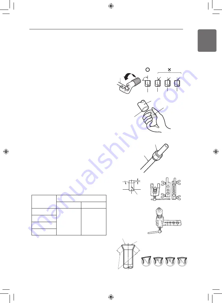
Step 1. Cut the pipes and the cable.

- Use the accessory piping kit or the pipes

purchased locally.

- Measure the distance between the indoor

unit and the outdoor unit.

- Cut the pipes a little longer than measured

distance.

- Cut the cable 1.5 m longer than the pipe

length.

Step 2. Burrs removal

- Completely remove all burrs from the cut

cross section of pipe/tube.

- Put the end of the copper tube/pipe to

downward direction as you remove burrs in
order to avoid to let burrs drop in the tubing.

Step 3. Putting nut on

- Remove flare nuts attached to indoor and

outdoor units, than put them on pipe/tube
having completed burr removal. (Not
possible to put them on after flaring work)

Step 4. Flaring work.

- Carry out flaring work using dedicated flaring

tool for R-410A refrigerant as shown below.

- Firmly hold copper tube in a bar(or die) as

indicated dimension in the table above.

Step 5. Check

- Compare the flared work with right figure.

- If flare is seemed to be defective, cut off the

flared section and do flaring work again.

Preparation for Piping

- Main cause of gas leakage is defect in flaring work. Carry out correct flaring work in the

following procedure.

- Use the de-oxidised copper as piping materials to install.

Inclined

Inside is shiny without scratches

Smooth all round

Even length

all round

Surface

damaged

Cracked Uneven

thickness

= Improper flaring =

Bar

Copper pipe

"A"

<Wing nut type>

<Clutch type>

Copper

tube

90°

Slanted   Uneven  Rough

Pipe

Reamer

Point down

Flare nut

Copper tube

Pipe diameter

(mm)

A (mm)

Wing nut type  Clutch type 

Ø 6.35

1.1~1.8

0~0.5

Ø 9.52

Ø 12.7

Ø 15.88

Summary of Contents for THERMA V Series

Page 1: ...ct Installation work must be performed in accordance with the national wiring standards by authorized personnel only Please retain this installation manual for future reference after reading it thoroughly Original instruction Copyright 2019 LG Electronics Inc All Rights Reserved MFL67212828 Rev 00_051519 ENGLISH FRANÇAIS ΕΛΛΗΝΙΚΆ ...

Page 2: ... Collective Continuous Installation for roof top use 33 Installation at Seaside 33 Seasonal wind and cautions in winter 35 INSTALLATION OF INDOOR UNIT 35 Electrical Wiring 38 Drill a Hole in the Wall 38 PIPING AND WIRING FOR OUTDOOR UNIT 38 Refrigerant Piping 39 Preparation for Piping 40 Connecting Pipe to Indoor Unit 40 Connecting Pipe to Outdoor Unit 43 Finalizing 44 Leakage test and Evacuation ...

Page 3: ...ING 78 How to enter service setting 78 Service setting 79 Service contact 80 Model information 81 RMC version lnformation 82 Open source license 83 INSTALLER SETTING 83 How to enter installer setting 84 Installer setting 86 3 Minutes Delay 87 Select Temperature Sensor 88 Dry Contact Mode 89 Central Control Address 90 Pump test run 91 Air heating set temp 92 Water heating set temp 93 DHW set temp 9...

Page 4: ... 108 Use External Pump 109 Pump Prerun Overrun 110 Data logging 111 Password Initialization 112 Power Supply Blockage SG Ready 113 Overview settings 115 COMMISSIONING 115 Check List before Starting Operation 116 Starting Operation 117 Starting Operation flow chart 117 Airborne Noise Emission 117 Limiting concentration R410A 118 Troubleshooting ...

Page 5: ...or unit Installation location constraints on installation site etc Chapter 5 Installation about the indoor unit Installation location constraints on installation site etc Constrains when accessories are installed Chapter 6 How to perform piping for refrigerant and wiring at the outdoor unit Refrigerant pipe connection between the indoor unit and the outdoor unit Electrical wiring at the outdoor un...

Page 6: ...circuit breaker Use this appliance on a dedicated circuit There is risk of fire or electric shock For electrical work contact the dealer seller a qualified electrician or an Authorized Service Center There is risk of fire or electric shock Always ground the unit There is risk of fire or electric shock Install the panel and the cover of control box securely There is risk of fire or electric shock R...

Page 7: ...ry Do not install the unit on a defective installation stand It may cause injury accident or damage to the unit Be sure the installation area does not deteriorate with age If the base collapses the unit could fall with it causing property damage unit failure and personal injury Do not install the water pipe system as Open loop type It may cause failure of unit Use a vacuum pump or inert nitrogen g...

Page 8: ...nit There is risk of fire or failure of unit Do not use the unit in a tightly closed space for a long time It may cause damage to the unit When flammable gas leaks turn off the gas and open a window for ventilation before turning the unit on There is risk of explosion or fire If strange sounds or smell or smoke comes from unit turn the breaker off or disconnect the power supply cable There is risk...

Page 9: ...roduct may operate during stop mode It is intended to protect the product Be careful that some part of the control box are hot There is risk of physical injury or burns When the unit is soaked flooded or submerged contact an Authorized Service Center There is risk of fire or electric shock Be cautious that water could not be poured to the unit directly There is risk of fire electric shock or unit ...

Page 10: ...o not step on or put anything on the unit There is risk of personal injury and failure of unit Use a firm stool or ladder when cleaning or maintaining the unit Be careful and avoid personal injury Do not turn on the circuit breaker or power under condition that front panel cabinet top cover control box cover are removed or opened Otherwise it may cause fire electric shock explosion or death The ap...

Page 11: ...d personnel mandated by the manufacturer or the authorized representative may be supplied in only one Community language which the specialized personnel understand This appliance is not intended for use by persons including children with reduced physical sensory or mental capabilities or lack of experience and knowledge unless they have been given supervision or instruction concerning use of the a...

Page 12: ... to Water Heat Pump Before starting installation please make it sure that all parts are found inside the product box INSTALLATION PART Item Image Quantity Installation Manual 1 Remote Controller Cable OK 1 Sensor Holder 1 Water Tank Temperature Sensor 1 Strainer 1 Screw 4 ...

Page 13: ...nstallation Model Information Factory Model Name A H U W 1 6 6 T 3 A H N W 1 6 6 T 3 Serial Number Function T High temperature Electrical ratings 6 1 phase 220 240 V 50 Hz Heating Capacity kW 16 16 kW Model Type W DC Inverter Heat Pump Classification U Outdoor Unit Air to Water Heat Pump Function T High temperature Heater Electrical ratings 6 1 phase 220 240 V 50 Hz Heating Capacity kW 16 16 kW Mo...

Page 14: ...Chassis Classification U Outdoor Unit Classification U Outdoor Unit Refrigerant A R410A High Temperature Electrical ratings 1 1Ø 220 240 V 50 Hz Heating Capacity kW 16 16 kW H Air to Water Heat Pump H N 16 1 0 H N K 3 Serial number Platform Chassis code K K3 Chassis Classification N Indoor Unit Classification N Indoor Unit High Temperature Heater Electrical ratings 1 1Ø 220 240 V 50 Hz Heater Capa...

Page 15: ...pliances were tested at atmospheric pressure Type Air to water Heat Pump For High Temperature Model Unit Indoor Outdoor Power Supply Ø V Hz 1 220 240 50 Capacity Heating kW 1 16 kcal h 13 760 Btu h 54 600 Net Weight kg lbs 84 185 89 196 Refrigerant Type R134a R410A Amount kg lbs 1 8 3 9 3 8 8 3 Sound Power Level PWL dB A 63 63 Maximum Running Current A 20 2 18 9 ...

Page 16: ...16 GENERAL INFORMATION ENGLISH Parts and Dimensions Indoor unit External unit mm ...

Page 17: ...eaving Water Pipe Male PT 1 inch 2 Entering Water Pipe Male PT 1 inch 3 Refrigerant Pipe Ø 9 52 mm 4 Refrigerant Pipe Ø 15 88 mm 5 Control Box PCB and terminal blocks 6 Flow Switch Minimum operation range at 15 LPM 7 Plate Heat Exchanger Heat exchange between refrigerant and water Description ...

Page 18: ...Heating Capacity 16 kW U3 Chassis unit mm 4 holes for anchor bolts 390 360 330 Supporter 1 380 165 165 490 620 950 390 1 356 Outdoor unit External No Name 1 Liquid side Service Valve 2 Gas side Service Valve 3 Air discharge Grill Description ...

Page 19: ...SH Control Parts Control Box Indoor Unit 2 1 Description No Name Remark 1 Terminal blocks The terminal blocks allow easy connection of field wiring 2 Main PCB The main PCB Printed Circuit Board controls the functioning of the unit ...

Page 20: ... setting value OK button When you save the menu s setting value On Off button When you turn ON OFF the AWHP OK Operation display window On Off button OK button Back button Up Down Left Right button Wiring Diagram Indoor Unit Refer to the wiring diagram inside the control box Circuit Diagram Indoor Unit Refer to the circuit diagram inside the front panel Wiring Diagram Outdoor Unit Refer to the att...

Page 21: ...21 GENERAL INFORMATION ENGLISH Wiring Diagram Indoor Unit ...

Page 22: ...22 GENERAL INFORMATION ENGLISH Wiring Diagram Outdoor Unit ...

Page 23: ...staller should optimize the installation scene according to the installation conditions Floor Heating only Floor Heating Hot water Hot water only Floor heating loop Fan coil unit Radiator Floor heating loop Fan coil unit Sanitary water tank Hot water Cold water supply Radiator Sanitary water tank Hot water Cold water supply Pump 3way valve Bypass valve ...

Page 24: ...cumulator High Pressure Sensor Strainer Electronic Expansion Valve Low Pressure Sensor Ref In Ref Out Water In Charging port Flow Switch Water in Temperature sensor Water out Temperature sensor Sanitary tank Or Floor Heating Discharge Temperature sensor Suction Temperature sensor Water side e d i s A 0 1 4 R e d i s a 4 3 1 R 24 GENERAL INFORMATION ENGLISH ...

Page 25: ...act is not applied to the unit Attach the ropes to the unit at an angle Ⓐ of 40 or less Use only accessories and parts which are of the designated specification when installing Indoor Unit Outdoor Unit Sub line 40º or less Line supporter Air outlet grille Intake hole Corner Handle Always hold the unit by the corners as holding it by the side intake holes on the casing may cause them to deform Sub ...

Page 26: ...nstallation in a place where acidic solution and spray sulfur are often used Do not use unit under any special environment where oil steam and sulfuric gas exist It is recommended to fence round the outdoor unit in order to prevent any person or animal from accessing the outdoor unit If installation site is area of heavy snowfall then the following directions should be observed Make the foundation...

Page 27: ...n neighboring floor Location with much humidity around Location where ventilation is good It is recommended to install the outdoor unit at a place with a lot of sunshine as possible as Location where water gathers since the floor is not even When installing the outdoor unit in a place that is constantly exposed to a strong wind like a coast or on a high story of a building secure a normal fan oper...

Page 28: ...h service space The unit of values is mm Outdoor Unit The following values are the least space for installation If any service area is needed for service according to field circumstance obtain enough service space The unit of values is mm Unit mm 400 520 300 Service space front side 330 600 Piping space front side Service space left side 100 100 100 100 200 1080 1080 H Beam supporter space Unit mm...

Page 29: ...ve installation 100 or more 100 or more 100 or 100 or more more 500 or less more 1000 or 100 or more 500 or less more 1000 or 150 or more 150 or 150 or more more Unit mm 500 or less more 1000 or 300 or more 100 or more 200 or more 1000 or more 300 or more 100 or more 1000 or more 200 or more Unit mm ...

Page 30: ...e side Ú Obstacle height of discharge side is higher than the unit Stand alone installation 500 or more 500 or less more 1000 or 500 or more 1000 or more 500 or less 1000 or more 1000 or more 100 or more 100 or more Unit mm H L L H L H 100 or more 500 or more 500 or less more 1000 or L H 250 or more 1000 or more Unit mm Collective installation ...

Page 31: ...llation L H L H L H 300 or more 1000 or more 500 or less more 1000 or L H 300 or more 1250 or more 5 5 5 100 or more 100 or more Unit mm L H L H H L 100 or more 500 or more 500 or less more 1000 or H L 300 or more 1000 or more L H L H H L 300 or more 1500 or more 500 or less more 1000 or H L 300 or more 1500 or more 100 or more 100 or more Unit mm ...

Page 32: ...to let in snow or rain Install the outdoor unit not to come in contact with snow directly If snow piles up and freezes on the air suction hole the system may malfunction If it is installed at snowy area attach the hood to the system Install the outdoor unit at the higher installation console by 50cm than the average snowfall annual average snowfall if it is installed at the area with much snowfall...

Page 33: ...upplier for the additional anticorrosion treatment Seasonal wind and cautions in winter Sufficient measures are required in a snow area or severe cold area in winter so that product can be operated well Get ready for seasonal wind or snow in winter even in other areas Install a suction and discharge duct not to let in snow or rain Install the outdoor unit not to come in contact with snow directly ...

Page 34: ...ground so that the unit will not cause any operating vibration or noise after installation Fix the unit securely by means of the foundation bolts Prepare 4sets of M12 foundation bolts nuts and washers each which are available on the market It is best to screw in the foundation bolts until their length are 20mm from the foundation surface 75 Flat washer Anchor bolt Spring washer Nut Anti vibration ...

Page 35: ... a cord set complying with the national regulation The connecting cable connected to the outdoor unit should be complied with IEC 60245 or HD 22 4 S4 This equipment shall be provided with a cord set complying with the national regulation In order to avoid a hazard due to inadvertent resetting of the thermal cut out this appliance must not be supplied through an external switching device such as a ...

Page 36: ...elow Round pressure terminal Power wire Precautions when laying power wiring Make sure that the screws of the terminal are free from looseness WARNING For wiring use the designated power wire and connect firmly then secure to prevent outside pressure being exerted on the terminal block Use an appropriate screwdriver for tightening the terminal screws A screwdriver with a small head will strip the ...

Page 37: ...upply systems for equipment with rated current 75 A European International Technical Standard setting the limits for harmonic currents produced by equipment connected to public low voltage systems with input current 16 A of 75 A per phase Circuit Breaker Specification Perform the electrical wiring work according to the electrical wiring connection All wiring must comply with local requirements Sel...

Page 38: ... m If the pipe length is longer than 7 5 m additional charge of the refrigerant is required according to the table Example If 16 kW model is installed at a distance of 50 m 1 700 g of refrigerant should be added according to following formula 50 7 5 x 40 g 1 700 g 2 Rated capacity of the product is based on standard length and maximum allowable length is based on the product reliability in the ope...

Page 39: ...flaring work Step 4 Flaring work Carry out flaring work using dedicated flaring tool for R 410A refrigerant as shown below Firmly hold copper tube in a bar or die as indicated dimension in the table above Step 5 Check Compare the flared work with right figure If flare is seemed to be defective cut off the flared section and do flaring work again Preparation for Piping Main cause of gas leakage is ...

Page 40: ...Step 1 Pre tightening Align the center of the pipes and sufficiently tighten the flare nut by hand Step 2 Tightening Tighten the flare nut with a wrench Tightening torque is as following Indoor unit tubing Flare nut Pipings Torque wrench Indoor unit tubing Open end wrench fixed Connection pipe Flare nut Outside diameter Torque mm kgf m 6 35 1 8 2 5 9 52 3 4 4 2 12 7 5 5 6 6 15 88 6 6 8 2 19 05 9 9...

Page 41: ...e piping Putty or insulating material produced locally Drain hose if necessary Connecting wire Connection pipe Wiring Procedure for Power Cable and Connecting Cable Step 1 Disassemble the side panel from the outdoor unit by loosing screws Step 2 Connect Power cable to Main Power Terminal and Connecting cable to Control Terminal respectively See below figure for detailed information When connecting...

Page 42: ... tightened burn out of the wire can be occurred Check the specification of power source such as phase voltage frequency etc Confirm that electrical capacity is sufficient Be sure that the starting voltage is maintained at more than 90 percent of the rated voltage marked on the name plate Confirm that the cable thickness is as specified in the power sources specification Particularly note the relat...

Page 43: ...t with thermal insulation material and secure it with two kinds of vinyl tape Tape the refrigerant pipe power cable and connecting cable from down to up Secure the taped pipe is along with the exterior wall Form a trap to prevent water entering the room and electrical part Fix the taped pipe onto the wall by saddle or equivalent Trap is required to prevent water from entering into electrical parts...

Page 44: ... test Connect the manifold valve with pressure gauges and dry nitrogen gas cylinder to this service port with charge hoses Be sure to use a manifold valve for leakage test If it is not available use a stop valve for this purpose The Hi knob of the manifold valve must always be kept close Pressurize the system to no more than 3 0 Mpa with dry nitrogen gas and close the cylinder valve when the gauge...

Page 45: ...wise to fully open the valve Turn the valve stem of gas side valve counter clockwise to fully open the valve Loosen the charge hose connected to the gas side service port slightly to release the pressure then remove the hose Replace the flare nut and its bonnet on the gas side service port and fasten the flare nut securely with an adjustable wrench This process is very important to prevent leakage...

Page 46: ...r is not permitted Before starting wiring job the main electricity supply should be turned off until wiring is completed When adjusting or changing wiring the main electricity supply should be turned off and ground wire should be connected securely Installation place should be free from the attack of wild animal For example mice s wire attacking or frog s entering into the indoor unit may cause cr...

Page 47: ... AC Connection for Main Pump 3WAY VALVE A THERMOSTAT Default 230 V AC PUMP A L N L L1 N N L1 L L2 1 2 3 4 5 6 8 9 7 10 Water flow switching between under floor heating and DHW tank heating 3 A 4 B Connection for 3rd Party controller 3rd PARTY CONTROLLER 3 A 4 B Connection for Indoor unit communication COMM Terminal Block 1 Terminal Block 2 Terminal Block 3 Terminal Block 4 You should separate the ...

Page 48: ... How to connect wirings Communication cable Power cable Earth 3 A 4 B Terminal block of indoor unit Terminal block of indoor unit Terminal block of outdoor unit ODU B ODU A IDU B IDU A CEN B CEN A DRY1 DRY2 GND 12V Communication cable Power cable ...

Page 49: ...l that inner section of the pipe should not be defective For example no weldments or no burrs are found inside the pipe Drain piping should be provided in case of water discharge by the operation of the safety valve This situation can be happened when the internal pressure is over 3 0 bar and water inside the indoor unit will be discharged to drain hose While connecting water pipes followings shou...

Page 50: ...re being stabilized Step 6 If following conditions are satisfactory then go to step 7 pipe insulation Otherwise go to step 3 Pressure gauge indicates 2 0 bar Note that sometimes pressure in decreased after step 5 due to water charging inside expansion vessel No air purging sound is heard or no water drop are popping out from air vent Pipe Insulation Purpose of water pipe insulation is To prevent h...

Page 51: ... sides of the pump to clean and repair the pump 3 Install the flexible joint 3 to prevent noise and vibration transferred from the pump 4 Install the pressure gauge 4 to monitor the water pressure from water tank Option 5 Install the expansion tank 5 to accommodate the water contracted or expanded from the temperature difference and to supply the water 6 After the installation of water pipe system...

Page 52: ...for assembly Install the service port facing downward Within left right 45 degrees Check if there is any leakage on the connecting part Clean the strainer periodically Once a year or more frequent shut off valve 2 Pump 1 Flexible joint 3 Pressure gauge 4 Water supply valve 6 water tank 9 Indirect heating type Expansion tank 5 Heat exchange coil 8 water tank temperature sensor 7 shut off valve 2 Pu...

Page 53: ...to use a magnetic or cyclone filter which can remove small particles Small particles may damage the unit and will NOT be removed by the standard filter of the heat pump system Water quality check should be implemented before completing the installation of system Detailed guide can be found in the table as below CAUTION Water contents Value pH 7 5 9 0 Conductivity 10 500 uS cm TDS Total dissolved s...

Page 54: ...e condition in Installation mode of remote controller Refer to page 109 and 161 Antifreeze type Antifreeze mixing ratio 0 C 5 C 10 C 15 C 20 C 25 C Ethylene glycol 0 12 20 30 Propylene glycol 0 17 25 33 Methanol 0 6 12 16 24 30 Use only one of the above antifreeze If a antifreeze is used pressure drop and capability degradation of the system can be occurred If one of antifreezes is used corrosion ...

Page 55: ... temperature PQRSTA0 Dry Contact To receive on off external signal PDRYCB000 Dry Contact For Thermostat PDRYCB300 DHW Tank Single Heating Coil To generate and store hot water OSHW 200F 200L OSHW 300F 300L OSHW 500F 500L DHW Tank Double Heating Coil OSHW 300FD 300L Thermistor for DHW Tank To control hot water temperature of DHW tank PHRSTA0 Meter Interface To measure production consumption power PE...

Page 56: ...Controller To connect external controller using modbus protocol 3way valve and actuator A To control water flow for hot water heating or floor heating To control water flow when installing 3rd party boiler B To control close open mode of solar circuit 3 wire SPDT Single Pole Double Throw type 230 V AC External Pump To retain sufficient capacity using additional pump Smart Grid To control operation...

Page 57: ...ectro mechanical type thermostat has internal delay time to protect compressor In that case mode change can takes time more than user s expectation Please read thermostat manual carefully if the unit does not response quickly Setting temperature range by thermostat can be different with that of the unit The heating or cooling set temperature should be chosen within the setting temperature range of...

Page 58: ... required 2 Electric circuit such as display LED buzzer etc is included in the thermostat and electric power supply is required 3 Thermostat generates Heating ON or Heating OFF signal according to user s heating target temperature Yes Heating Only 3 230 V Electrical 2 Yes Heating Only 3 230 V Mechanical 1 Supported Operating Mode Power Type 5 ft 1 5 m Direct Sun ray contact area no no no yes Therm...

Page 59: ...nnect wire N as mechanical type thermostat does not require electric power supply L Live signal from PCB to thermostat N Neutral signal from PCB to thermostat H Heating signal from thermostat to PCB Final check DIP switch setting Set DIP switch No 8 to ON Otherwise the unit can not recognize the thermostat Remote Controller Thermostat text is displayed on the remote controller Button input is proh...

Page 60: ...elow procedures step 1 step 4 3 A 4 B 3 A 4 B 3rd PARTY CONTROLLER DC 5 V 3rd PARTY CONTROOLER CN_COM CN_COM Indoor PCB Indoor PCB Step 1 Check if the power of the unit is turned off Step 2 Disassemble front panels and distinguish control box Indoor of the unit Step 3 Check if the harness White is inserted fully to the indoor unit PCB CN_COM Step 4 Connect the 3rd party controller to terminal bloc...

Page 61: ...ions can be controlled in the central control linked state Operation Stop Desired temperature Hot water operation stop Warm water temperature Full lock Etc How to Installation PI485 Fix the PI485 PCB as shown in below images For detailed installation method refer to PI485 Installation Manual Product Heating Capacity 12 kW 14 kW 16 kW U3 Chassis ...

Page 62: ...end to wash out inside of the sanitary water tank after installation It ensures generating clean hot water Near the sanitary water tank there should be water supply and water drain to easy access and maintenance Set the maximum value of the temperature control device of sanitary tank General Information supports following 3way valve 1 SPDT Single Pole Double Throw Three wires consist of Live1 for ...

Page 63: ... used to turn the unit On Off after getting the signal from external sources How to install dry contact Parts of Dry contact Follow below procedures step 1 step 4 Step 1 Check if the power of the unit is turned off Step 2 Disassemble front panels and distinguish terminal block in Indoor PCB Step 3 Connect cable to the unit PCB CN_CC fully Step 4 Then Insert harness to the dry contact PCB CN_INDOOR...

Page 64: ... does not supply this section Field supply For input contact voltage DC 12 V 24 V Notes Do not input the voltage signal in NON VOLT setting mode otherwise it will cause serious damage jvtt v jvtt mhu olh jvvs sv tpkksl opno Thermostat LG does not supply this section Field supply For input contact closure only No power input Setting of Contact Signal Input ...

Page 65: ...y stop only for indoor unit 4 Reattachment absence 5 Emergency stop of all indoor units It can be set only when indoor unit has emergency stop function Indoor PCB CN_EXT CN_EXT Indoor PCB Adapter Cable Indoor Unit Supplied Part X 0 5 m Max 10 m X Relay Circuit Power supply of relay SW PCB Field Installation Part Installation example 2 SW Single pole switch Select a part with contacts for extremely...

Page 66: ...ot matter if you change the color of the wire because of nonpolar Remote Temperature Sensor Remote temperature sensor can be installed any place a user wants to detect the temperature The function is not available for some products Installation condition Role and constraint while installation of remote air temperature sensor is very similar to that of thermostat Distance between the unit and the r...

Page 67: ...ooling heating devices do not affect the remote sensor Choose the place where the outlet of the cooling fan do not affect the remote sensor Choose the place where the remote sensor isn t affected when door is open NOTE For more information about installing Remote Temperature Sensor Please refer installation manual provided with Remote Temperature Sensor For system set up please read chapter 8 Espe...

Page 68: ...installed with buffer tank to retain sufficient capacity How to install external pump Follow below procedures step 1 step 3 Step 1 Check if the power of the unit is turned off Step 2 Disassemble front panels and distinguish terminal block in Indoor PCB Step 3 Connect signal cable to terminal block TB_EXT_PUMP fully External pump Voltage free TB_EXT_PUMP TB_EXT_PUMP Indoor PCB Indoor PCB ...

Page 69: ... 1 step 5 Step 1 Check if the power of the unit is turned off Step 2 Disassemble front panels and distinguish control box Indoor of the unit Step 3 Connect the USB cable to the indoor unit PCB CN_WF Blue until it clicks into place Step 4 Connect the Wi Fi modem to the USB cable fully Step 5 Refer to the image below to install the Wi Fi modem in the marked position USB Cable CN_WF CN_WF Indoor PCB ...

Page 70: ...ectric Operation SG1 SG2 Heating Domestic How Water SGN Open Open Normal Operation Normal Price Maintain operation status Maintain operation status SG1 Close Open Operation Off Utility lock High Price Forced internal operation off Forced internal operation off SG2 Open Close Operation On Recommend Low Price Target temperature change automatically depend on SG Mode value in installer setting Step 0...

Page 71: ...he unit to DHW water tank How to wire 3way valve A Follow below procedures Step 1 Step 2 Step 1 Uncover front cover of the unit Step 2 Find terminal block and connect wire as below W Live signal Water tank heating from PCB to 3way valve U Live signal Under floor heating from PCB to 3way valve N Neutral signal from PCB to 3way valve Type Power Operating Mode Supported SPDT 3 wire 1 220 240 V Select...

Page 72: ...erformance can be expected DIP Switch Setting General Information Indoor PCB OFF ON SW1 1 2 3 4 OFF ON 1 2 3 4 OFF is selected ON is selected OFF ON SW2 1 2 3 4 5 6 7 8 SW3 1 2 3 4 1 2 3 4 1 2 3 4 5 6 7 8 Turn off electric power supply before setting DIP switch Whenever adjusting DIP switch turn off electric power supply to avoid electric shock CAUTION 72 CONFIGURATION ENGLISH ...

Page 73: ...sory installation information 2 3 6 7 2 3 2 3 Unit Outdoor unit is installed Unit Outdoor unit DHW tank is installed DHW tank Only Cycle 4 Heating Only Flow Switch Flow Sensor Detection 5 Always Selecting electric heater capacity Electric heater is not used Thermostat installation information 8 8 Thermostat is NOT installed Thermostat is installed 1 2 3 4 5 6 7 8 5 While water pump is on ...

Page 74: ...e 2 2 Common 3rd party SIEMENS 3 3 4 4 Reserved Reserved 1 2 3 4 Description Setting Default Option Switch 3 Description Setting Default Description Description Setting Setting Default Default Remote Air Sensor ANTIFREEZE Reserved Reserved 1 1 Remote sensor is not installed Remote sensor is installed 2 Antifreeze mode not use 3 3 4 4 Reserved Not Use 1 2 3 4 ...

Page 75: ...ormation Indoor Cycle PCB All pins are reserved Don t select Outdoor Cycle PCB All pins are reserved Don t select OFF OFF is selected ON is selected ON Default SW2 1 2 3 4 5 6 7 OFF OFF is selected ON is selected ON Default SW2 1 2 3 4 5 6 7 ...

Page 76: ...th sensor problems The outdoor unit is operating under emergency mode operation condition which is configured by DIP switch No 4 of the unit PCB Heavy trouble a problem is found inside the outdoor unit As the outdoor unit has problem the emergency mode operation is performed by electric heater located in the unit Option Trouble a problem is found for option operation such as water tank heating In ...

Page 77: ...emergency operation mode When DHW is not warming up while emergency operation please check if DHW sensor and related wiring are all Ok Emergency operation is not automatically restarted after main electricity power is reset In normal condition the product operating information is restored and automatically restarted after main electricity power is reset But in emergency operation automatic re star...

Page 78: ...ting category and press OK button to move to the service setting list Service setting You can set the product service functions Some functions may not be displayed operated in some product types OK Menu Description Service contact Check and input the service center phone number that you can call when there is service issue Model information View product and capacity information RMC Version Informa...

Page 79: ... you can call when there is service issue In the service setting list select the service contact point and press OK button to move to the detail screen While edit button is selected press OK button to move to the edit screen change it and press OK button to change the service contact point OK OK ...

Page 80: ...d In the service setting list select model information category and press OK button to move to the detail screen The unit capacity 1 kWh 1 kBtu 0 29307 kWh is the result calculated based on Btu There may be a small difference between calculated and actual capacity Ex If the unit capacity is 18 kBtu it is displayed as 5 kWh OK ...

Page 81: ...ERVICE SETTING ENGLISH RMC version lnformation View the remote controller software version In the service setting list select the RMC version information and press OK button to move to the detail screen OK ...

Page 82: ...ICE SETTING ENGLISH Open source license View the remote controller s open source license In the service setting list select the open source license category and press OK button to move to the detail screen OK ...

Page 83: ...001 OK OK INSTALLER SETTING How to enter installer setting NOTE Some categories of the installer setting menu may not be available depending on the product function or the menu name may be different The installer setting mode is the mode to set the remote controller s detail function If the installer setting mode is incorrectly set it may cause product failure user s injury or property damage It m...

Page 84: ...eating set temp setting Adjusting range of Setting Air Temperature in heating mode Water heating set temp setting Adjusting range of Setting Heating Flow Temperature in heating mode DHW Set Temp setting Setting DHW set temperature Tank disinfection setting 1 Setting start maintain time for pasteurisation Tank disinfection setting 2 Setting pasteurisation temperature Tank setting 1 Setting start te...

Page 85: ...oduct set the operation option value in SG1 step IDU Address Verification Function to check the result of Auto Addressing of outdoor unit with remote control CN_EXT Function to set external input and output control according to DI DO set by customer using dry contact port of indoor unit Determine the use of the contact port CN_EXT mounted on the indoor unit PCB Use External Pump Set up to control ...

Page 86: ...ISH 3 Minutes Delay Temporarily eliminates the 3 minute delay function of the outdoor unit Comp Factory use only In the installer setting list select 3 Minutes Delay category and press OK button to move to the detail screen OK ...

Page 87: ...ting temperature as air temperature or leaving water temperature is determined In the installer setting list Select Temperature Sensor category and press OK button to move to the detail screen NOTE Air temperature as setting temperature is ONLY available when Remote Air Sensor Connection is enabled and Remote Air Sensor Connection is set as 02 OK Value Water Air ...

Page 88: ...ing values using left right button Value Auto manual NOTE For dry contact mode related detail functions refer to the individual dry contact manual What is dry contact It means the contact point signal input when the hotel card key human body detection sensor etc are interfacing with the air conditioner Added system functionality by using external inputs dry contacts and wet contacts ...

Page 89: ...rol address of the unit In the installer setting list select Central Control Address category and press OK button to move to the detail screen OK NOTE Enter address code as hexadecimal value Front Central Control Gr No Back side Central control indoor the number NOTE This function is not available for monobloc ...

Page 90: ... The pump test run is the function to test run by operating the water pump This function can be used for air vents flow sensors and others In the installer setting list Pump Test run category and press OK button to move to the detail screen OK ...

Page 91: ...staller setting list select Air heating set temp category and press OK button to move to the detail screen Upper lower limit default value is in C OK Value Default Range Max 30 30 24 Min 16 22 16 Only available when remote air temperature sensor is connected Accessory PQRSTA0 should be installed Also Remote air sensor connection should be set properly CAUTION ...

Page 92: ...rature range when leaving water temperature is selected as setting temperature In the installer setting list select Water heating set temp category and press OK button to move to the detail screen Upper lower limit default value is in C OK Value Default Range Max 80 80 50 Min 30 46 30 ...

Page 93: ...etting temperature range when DHW temperature is selected as setting temperature In the installer setting list select DHW set temp category and press OK button to move to the detail screen Upper lower limit default value is in C OK Value Range Max 80 50 Min 45 30 ...

Page 94: ...e date when the disinfection mode is running Start time Determining the time when the disinfection mode is running Max temp Target temperature of disinfection mode Duration time Duration of disinfection mode Time Start time Max temp Duration time Water temperature Inside DHW Temperature profile of Disinfection operation NOTE DHW heating should be enable If Disinfection active is set as Not use tha...

Page 95: ... INSTALLER SETTING ENGLISH Tank setting 1 In the installer setting list select tank setting 1 category and press OK button to move to the detail screen OK Value Range Max outdoor temp 80 40 Min temp 20 1 ...

Page 96: ...LLER SETTING ENGLISH Tank setting 2 In the installer setting list select tank setting 2 category and press OK button to move to the detail screen OK Value Range Hysteresis 4 2 Heating priority Floor heating DHW ...

Page 97: ...ank heater will be turned on when the water temperature is below 70 C Example If Heating priority is set as DHW that means heating priority is on DHW heating DHW is heated by AWHP compressor cycle and water heater In this case the under floor can not be heated while DHW heating On the other hand if the Heating priority is set as Floor heating that means heating priority is on under floor heating D...

Page 98: ...me DHW tank heating can be stopped It is also regarded as time gap between DHW tank heating cycle Boost heater delay time This time duration defines how long time DHW tank heater will not be turned on in DHW heating operation Example of timing chart DHW tank heating is enabled DHW tank heater is enabled DHW tank heating operation DHW tank heater operation 1 active 0 not active A Active time S Stop...

Page 99: ...the heating air temperature Thermal On Off temperature according to the field environment in preparation for heating or heating claim You can set the following setting values using left right button Value Description TH On TH Off Type0 0 5 C 1 5 C Type1 1 C 2 C Type2 2 C 3 C Type3 3 C 4 C ...

Page 100: ...t the heating water temperature Thermal On Off temperature according to the field environment in preparation for heating or heating claim You can set the following setting values using left right button Value Description TH On TH Off Type0 2 C 2 C Type1 3 C 3 C Type2 4 C 4 C Type3 1 C 1 C ...

Page 101: ...n heating mode the control reference water temperature position setting If the air leaving water temperature selection setting is set to leaving water temperature Change setting values using left right button The function is not available for some products Value Outlet Default Inlet ...

Page 102: ... putting the water pump s rest time Installer setting function to set water pump operation delay time option in heating mode In the installer setting list select Pump setting in heating category and press OK button to move to the detail screen OK Type Time setting Operation continue On 1 min 60 min Off 1 min 60 min ...

Page 103: ...to prevent pump failure and PHEX freezing Water pump off After 20 consecutive hours disable enable the logic that drives the water pump by itself In the installer setting list select Forced operation category and press OK button to move to the detail screen OK Type Use Not use Oper Cycle 20 hours 180 hours Oper Time 1 min 10 min ...

Page 104: ...escription D C Automatic When power is applied to the product the unit when the contact point is on in Dry Contact installed state recognizes Dry Contact installation D C Not Installed Do not use install Dry Contact D C Installed Use install Dry Contact NOTE CN_CC is the device connected to the unit to recognize and control the external contact point ...

Page 105: ...lt Use Step 0 Step 1 Step 2 Smart Grid SG It is the function to enable disable the SG Ready function and to set the reference value at SG2 step In the installer setting list select Smart Grid SG category and press OK button to move to the detail screen OK ...

Page 106: ...t of Auto Addressing of outdoor unit with remote control IDU address setting function is available from indoor unit In the installer setting list select IDU Address Verification and press OK button to move to the detail screen OK 106 INSTALLER SETTING ENGLISH ...

Page 107: ...l external input and output according to DI type set by customer using CN EXT Port In the installer setting list select CN EXT Port category and press OK button to move to the detail screen Value Not use Simple Operation Simple Dry Contact Single emergency stop OK ...

Page 108: ...ING ENGLISH Use External Pump This function can be set to control the external water pump In the installer setting list select Use External Pump category and press OK button to move to the detail screen Value Not use Use ...

Page 109: ... is operated This is a function that allows heat exchange to work smoothly Pump Overrun is a function to prevent water pump failure and to help mechanical life If the water pump has been off for 20 hours Water pump will operate for the set time OK Value Default Setting Range Prerun 1 min 1 10 min Overrun 1 min 1 10 min ...

Page 110: ...move to the detail screen OK NOTE Error history lookup range 50 Error history information Item date time mode including Off set temperature incoming temperature outgoing temperature room temperature Hot water operation stop Hot water set temperature Hot water temperature Outdoor unit On Off Error code Number of Display Within 50 Save criteria ν ν Error occurred released ON OFF of outdoor unit oper...

Page 111: ...t in the remote controller In the installer setting list select the password initialization setting category and press OK button to move to the detail screen When you press initialization button a popup screen appears and when you press check button password initialization starts and the user password is changed to 0000 OK ...

Page 112: ...increased depending on the parameter Mode SG Mode SG set temperature α depending on the below parameter Step 0 DHW 5 C Step 1 H P 2 C DHW 5 C Step 2 H P 5 C DHW 7 C 1 1 Switch on command The command activates the compressor Optionally electrical booster heaters can be activated to utilize electricity surpluses Power Supply Blockage SG Ready The heat pump operated automatically by the power supply ...

Page 113: ...st run Air heating set temp Water heating set temp DHW set temp Tank disinfection setting 1 2 Tank setting 1 Tank setting 2 DHW time setting TH on off Variable heating air TH on off Variable heating water Installer Central Control Address 88 89 90 91 92 93 94 95 96 97 98 100 101 102 103 104 105 106 107 108 82 83 84 85 Heating temp setting Pump setting in heating Forced operation CN_CC Smart Grid S...

Page 114: ...114 INSTALLER SETTING ENGLISH CN_EXT Use External Pump Pump Prerun Overrun Data logging Password Initialization 109 110 111 112 113 ...

Page 115: ...ceed 3 0 bar During water charging air should be taken out through the hole of the air purge If water does not splash out when the tip at the top of the hole is pressed then air purging is not completed yet If well purged the water will splash out like fountain Be careful when testing air purge Splashed water may make your dress wet Two shut off valves located at the end of water inlet pipe and wa...

Page 116: ... 2 3 4 Starting Operation Check before Starting Operation 1 Check to see whether there is any refrigerant leakage and check whether the power or transmission cable is connected properly 2 Confirm that 500 V megger shows 2 0 MΩ or more between power supply terminal block and ground Do not operate in the case of 2 0 MΩ or less NOTE Never carry out mega ohm check over terminal control board Otherwise...

Page 117: ...ther precautions are required Factor that influence the actual level of exposure of the workforce include the characteristics of the work room and the other sources of noise i e the number of equipment and other adjacent processes and the length of time for which an operator exposed to the noise Also the permissible exposure level can vary from country to country This information however will enab...

Page 118: ...re is too low If water inlet temperature is below 5 C the unit does not operated for the sake of system protection Wait while unit warms up the water inlet temperature If water inlet temperature is below 15 C in heating operation the unit does not operated for the sake of system protection Wait while unit warms up to 18 C the water inlet temperature If you are not using the back up heater accessor...

Page 119: ...CH05 Indoor unit outdoor unit communication error No signal communication between indoor unit outdoor unit CH08 Water tank temperature sensor error Water tank temperature sensor disconnection or short circuit CH09 Indoor unit EEPROM error Communication between the micro processor the EEPROM Error due to EEPROM damage CH11 Indoor unit inverter PCB communication error No signal communication between...

Page 120: ...essure of inverter compressor Excessive drop of low pressure of inverter compressor causing compressor OFF bc36 Low pressure ratio error of inverter compressor High pressure low pressure ratio of inverter compressor is maintained at below 1 8 for 3 min or more bc40 Inverter compressor CT sensor defect Inverter compressor CT sensor defect bc41 Inverter compressor discharge pipe temperature sensor d...

Page 121: ...verter input 2 8 1 Inverter DC Link high voltage error Inverter DC voltage recharge causing compressor OFF 2 9 1 Inverter compressor overcurrent Inverter compressor activation failure or increase of CT value 3 2 1 Excessive rise of inverter compressor discharge temperature Excessive rise of inverter compressor discharge temperature causing compressor OFF 3 4 1 Excessive rise of high pressure of in...

Page 122: ...or Inverter PCB EEPROM error 6 2 1 Excessive rise of inverter heatsink temperature Inverter PCB heat generation causing the rise of heatsink temperature 6 7 1 Outdoor Unit Fan Lock Restriction of Outdoor Unit Fan 7 3 1 Overcurrent Peak detected at inverter input Error by overcurrent detection at inverter input 8 6 1 Outdoor Unit Main PCB EEPROM Error Communication Fail Between Outdoor Unit Main MI...

Page 123: ......

Page 124: ... Inc EU Representative LG Electronics European Shared Service Center B V Krijgsman 1 1186 DM Amstelveen The Netherlands Manufacturer LG Electronics Inc Changwon 2nd factory 84 Wanam ro Seongsan gu Changwon si Gyeongsangnam do KOREA ...

Reviews: