- 6 -
RS-232C INPUT
(CONTROL/SERVICE)
REMOTE
CONTROL
DVI INPUT
S-VIDEO
AUDIO
VIDEO
MONITOR
OUTPUT
A/V
INPUT1
AUDIO
R
L
Antenna
AC INPUT
VIDEO
INPUT 2
COMPONENT
INPUT 1
COMPONENT
AUDIO INPUT
RGB INPUT
R
L/MOND
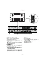
<Back Panel>
1. CONTROL LOCK / REMOTE CONTROL
2. RS-232C INPUT(CONTROL/SERVICE) PORT
Connect to the RS-232C port on a PC.
3. DVI INPUT / AUDIO INPUT / RGB INPUT
Connect the monitor output socket of the PERSONAL COM-
PUTER to this socket.
Note:
If you want to use RGB/DVI audio, we strongly recom-
mend that you use the cable that has a core, or the EMI Fillter
core along with separete cable.
4. COMPONENT INPUT
Connect DVD video outputs to Y, P
B
, P
R
of COMPONENT
INPUT and audio outputs to Audio sockets of AUDIO INPUT.
5. AUDIO/VIDEO IN SOCKETS (AV1)
Connect the audio/video out sockets of external equipment to
these sockets.
S-VIDEO/AUDIO IN SOCKETS
Connect the S-VIDEO out socket of an VCR to the
S-VIDEO
socket.
Connect the audio out sockets of the VCR to the audio sock-
ets as in
AV1
.
6. ANTENNA INPUT
7. POWER CORD SOCKET
This Monitor operates on an AC power. The voltage is indi-
cated on the Specifications page. Never attempt to operate
the Monitor on DC power.
8. AUDIO/VIDEO IN SOCKETS (AV2)
S-VIDEO/AUDIO IN SOCKETS
8
S
-V
ID
E
O
V
ID
E
O
A
U
D
IO
A
V
2
R
L/
M
O
N
O
3
4
5
7
6
1
2


