- 20 -
7. Adjustment of White Balance
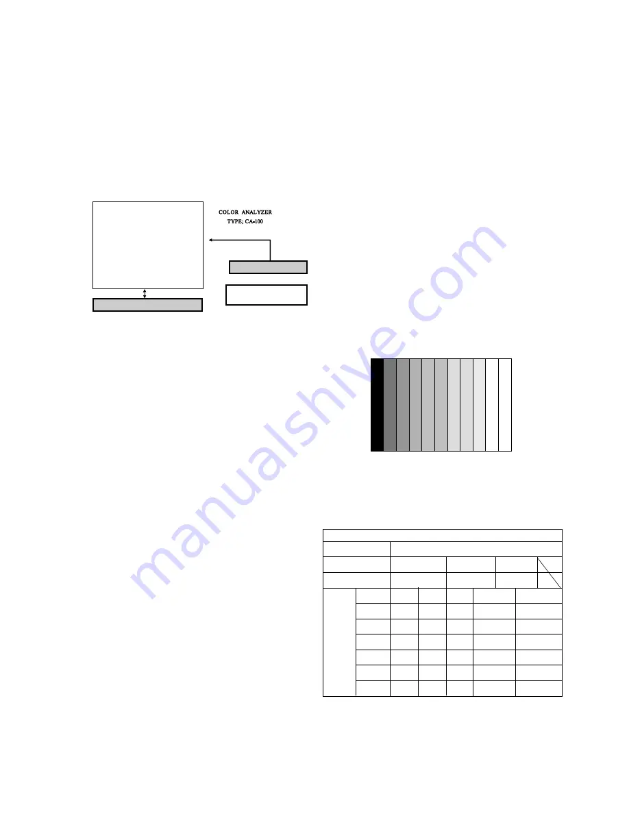
7-1. Required Equipment
Color Analyzer (CA-100 or same product)
7-2. Connection Diagram of Equipment for
Measuring
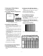
7-3. Adjustment of White Balance
O
Operate the Zero-calibration of the CA-100, then stick
sensor to PDP module surface when you adjust.
O
For manual adjustment, it is also possible by the following
sequence.
(1) Select white pattern of heat-run mode by pressing power
on key on remote control for adjustment then operate heat
run more than 15 minutes.
(2) Supply Gray Pattern (216 Level Full Size Pattern: Signal
level=0.59V±0.03V) signal to VIDEO input. (AV2 Input
60Hz) (Refer to Fig. 12)
(3) Press the FRONT-AV KEY on R/C for converting input
mode.
(4) To adjust, stick sensor to 216 Gray Level Pattern, press
ADJ key twice(White Balance) on remote control.
For adjustment and
D
,
E
on remote control for adjustment
mode to select Red Gain and Green Gain, press VOL +, -
Key and adjust it until color coordination becomes as
below.
[
216 Gray level=Signal level 0.59V±0.03V
X; 0.283±0.003, Y; 0.297±0.003
Color Temperature; 9,300¡K±500¡K
(5) Exit adjustment mode using
A
Key.
8. Auto Component Color Balance
8-1. Required Test Equipment
Pattern Equipment: MSP3240A or same product
(16 Gray Scale Pattern output(Component output Level:
0.7Vp-p)
8-2. Method of Auto RGB Color Balance
(1) Input RGB Source : Component 480p/576p 16 Gray Scale
Pattern
At this time, except Pb and Pr signal, only Y signal insert.
(2) Press ADJ KEY on R/C for adjustment.
(3) Press Vol. + KEY and operate To set.
(4) Auto-RGB OK means completed adjustment.
9. Auto RGB Color Balance
9-1. Required Test Equipment
Pattern Equipment: PC Pattern Generator (VG828, VG854,
801GF, MSP3240A)
(16 Gray Scale Pattern output(RGB output Level: 0.7Vp-p)
9-2. Method of Auto RGB Color Balance
(1) Input RGB Source : 16 Gray Scale Pattern output (RGB
output Level : 0.7Vp-p)
(2) Press ADJ KEY on R/C for adjustment.
(3) Press Vol. + KEY and operate To SET.
(4) Auto-RGB OK means completed adjustment.
10. Auto Adjustment Map(RS-232C)
Window
MSPG-2100 or
MSTG-5200
AV Signal Input
Full Size Pattern
216 Gray Level
RS-232C Serial Communication
60Hz
(Fig. 12) White Balance Adjustment
(Fig. 13) Auto RGB/ Component Color Balance Test Pattern
Type
Baud Rate
115200
Index
R Gain
G Gain
B Gain
R Offset
G Offset
B Offset
Data bit
8
Cmd1
Cmd2
j
a
j
b
j
c
j
d
j
e
j
f
Stop bit
1
Parity
NONE
RF-043A
Protocol
Setting
Data
Min Value
00(00)
00(00)
00(00)
00(00)
00(00)
00(00)
Max Value
255(FF)
255(FF)
255(FF)
255(FF)
255(FF)
255(FF)
RS232

