7
· Stand on suitable rubber mats (obtained locally, if necessary) to insulate you from grounds such as metal
floor strips and machine frames.
· Observe the special safety precautions when you work with very high voltages. These instructions are in
the safety sections of maintenance information. Use extreme care when measuring high voltages.
· Regularly inspect and maintain your electrical hand tools for safe operational condition.
· Do not use worn or broken tools and testers.
· Never assume that power has been disconnected from a circuit. First check that it has been powered off.
· Always look carefully for possible hazards in your work area. Examples of these hazards are moist floors,
non-grounded power extension cables, power surges, and missing safety grounds.
· Do not touch live electrical circuits with the reflective surface of a plastic dental mirror. The surface is
conductive such touching can cause personal injury and machine damage.
· Do not service the following parts with the power on when they are removed from their normal operating
places in a machine.
1. Power supply units
2. Pumps
3. Blowers and fans
4. Motorgenerators
and similar units. (This practice ensure correct grounding of the units.)
· If an electrical accident occurs
1. Use caution ; do not become a victim of yourself.
2. Switch off power.
3. Send another person to get medical aid.
Ch1. Service information
Summary of Contents for R580 Series U.ARC3BA9
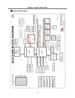
Page 17: ...17 System Block Diagram Chapter 3 System information ...
Page 27: ...27 Ch3 System information g Burn process completed as below and tab OK ...
Page 60: ...60 Ch5 Removing and replacing a part 5 Remove the HDD Shield ...
Page 63: ...63 Ch5 Removing and replacing a part 3 Remove the WLAN Module ...
Page 66: ...66 3 Remove the ODD Ch5 Removing and replacing a part 4 Remove the ODD Bezel Bezel ...
Page 69: ...69 69 Ch5 Removing and replacing a part 5 Remove the Keyboard 6 Remove the Retainer ...
Page 71: ...71 71 Ch5 Removing and replacing a part 3 Remove the Display Module ...
Page 74: ...74 Ch5 Removing and replacing a part 3 Remove the Keyboard deck ...
Page 79: ...79 Ch5 Removing and replacing a part 3 Remove the Mainboard Case ...
Page 86: ...86 Ch5 Removing and replacing a part 3 Remove the Hinge Cap ...
Page 98: ...NLCD07 NLCD05 NLCD09 NLCD03 NLCD01 NLCD04 NLCD08 NLCD02 NWEBC01 ...
Page 100: ...NMINI02 NMINI01 NKDECK01 NKDECK02 NRTN01 NKEYBD01 ...
Page 102: ...NMRY01 NMRY01 NMINI04 NTHMO01 NRBS01 NMINI03 NCPU01 NMLB01 ...
Page 105: ...NCVR02 NCVR03 NCVR01 NHDD02 NHDD01 NBATT01 NODD02 NODD01 NBOTM01 NBOTM03 NHDD03 NBOTM02 ...

