


4
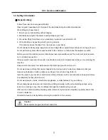
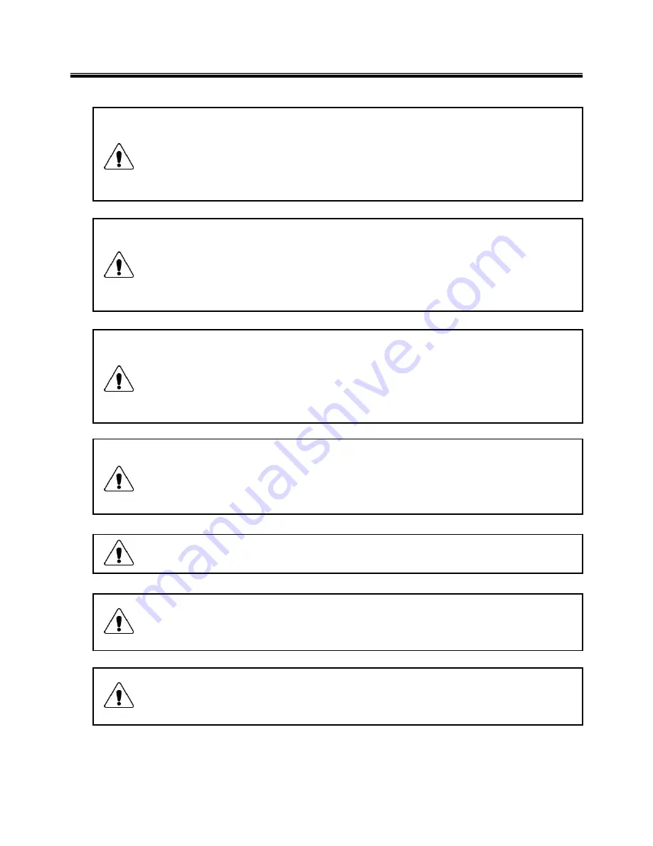
1-2. Safety notices
Warning
Before the computer is powered-on after part (FRU) replacement, make sure all screws, springs,
and other small parts are in place and are not left loose inside the computer. Verify this by
shaking the computer and listening for rattling sounds. Metallic parts or metal flakes can cause
electrical shorts.
Warning
some standby batteries contain a small amount of nickel and cadmium. Do not disassemble
a standby battery, recharge it, throw it into fire or water, or short-circuit it. Dispose of the battery
as required by local ordinances or regulations. Use only the battery in the appropriate parts
listing. Use of an incorrect battery can result in ignition or explosion of the battery
Warning
The battery pack contains small amounts of nickel. Do not disassemble it, throw it into fire or
water, or short-circuit it. Dispose of the battery pack as required by local ordinances or
regulations. Use only the battery in the appropriate parts listing when replacing the battery pack.
Use of an incorrect battery can result in ignition or explosion of the battery.
Warning
If the LCD breaks and the fluid from inside the LCD gets into your eyes or on your hands,
immediately was the affected areas with water for at least 15 minutes. Seek medical care if any
symptoms from the fluid are present after washing.
Warning
To avoid shock, do not remove the plastic cover that protects the lower part of the inverter card.
Warning
Though the main batteries have low voltage, a shorted or grounded battery can produce enough
current to burn personnel or combustible materials.
Warning
Before removing any part (FRU), turn off the computer, unplug all power cords from electrical
outlets, remove the battery pack, and then disconnect any interconnecting cables.
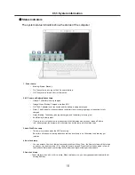
Ch1. Service information
Summary of Contents for R580 Series U.ARC3BA9
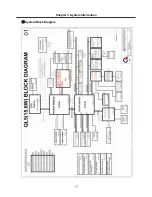
Page 17: ...17 System Block Diagram Chapter 3 System information ...
Page 27: ...27 Ch3 System information g Burn process completed as below and tab OK ...
Page 60: ...60 Ch5 Removing and replacing a part 5 Remove the HDD Shield ...
Page 63: ...63 Ch5 Removing and replacing a part 3 Remove the WLAN Module ...
Page 66: ...66 3 Remove the ODD Ch5 Removing and replacing a part 4 Remove the ODD Bezel Bezel ...
Page 69: ...69 69 Ch5 Removing and replacing a part 5 Remove the Keyboard 6 Remove the Retainer ...
Page 71: ...71 71 Ch5 Removing and replacing a part 3 Remove the Display Module ...
Page 74: ...74 Ch5 Removing and replacing a part 3 Remove the Keyboard deck ...
Page 79: ...79 Ch5 Removing and replacing a part 3 Remove the Mainboard Case ...
Page 86: ...86 Ch5 Removing and replacing a part 3 Remove the Hinge Cap ...
Page 98: ...NLCD07 NLCD05 NLCD09 NLCD03 NLCD01 NLCD04 NLCD08 NLCD02 NWEBC01 ...
Page 100: ...NMINI02 NMINI01 NKDECK01 NKDECK02 NRTN01 NKEYBD01 ...
Page 102: ...NMRY01 NMRY01 NMINI04 NTHMO01 NRBS01 NMINI03 NCPU01 NMLB01 ...
Page 105: ...NCVR02 NCVR03 NCVR01 NHDD02 NHDD01 NBATT01 NODD02 NODD01 NBOTM01 NBOTM03 NHDD03 NBOTM02 ...