


-8-
4
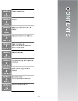
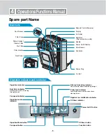
Operations/Functions Manual
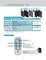
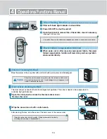
Spare part Name
Remote Control Receiver
Dust Sensor
Filter Case
Photo-Catalyst
Plasma Filter
Pre-Filter
Filter Handle
Front Panel
Display
Air Outlet
Safty Net:
–The inside of air outlet
Handle
Power On/Off Button
Odor Sensor
Controller
Power Plug
Air Inlet
Mainframe
Operation indicator and controller
Off timer indicator
Power On/Off button
Off timer button
Function button
Negative ion/ sterilization indicator
Purity level indicator
Level reflects how well the air purifier is
cleaning the air.
Filter self-checking indicator
Check the filter when indicated by the light.
Operation indicator
Fan speed indicator
Operation Mode button
Fan speed button
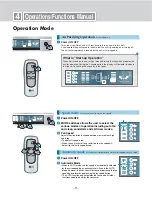
Operation mode
indicator
Dust/Odor indicator
Reflects how well air is moving
through the unit.
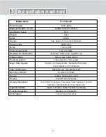
Summary of Contents for PS-M550WP
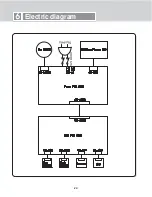
Page 22: ... 22 6 Electric diagram ...
Page 28: ... 28 PCB Circuit Diagram Parts Layouts DC PART Parts Layouts AC PART Parts Layouts 8 ...
Page 29: ... 29 8 PCB Circuit Diagram Parts Layouts DC PART Circuit Diagram ...
Page 30: ... 30 8 PCB Circuit Diagram Parts Layouts AC PART Circuit Diagram ...
Page 32: ... 33 ...