


-23-
7
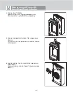
Troubleshooting and inspection direction
Please take a look at the panel arrangement and the circuit drawing.
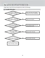
Complete Malfunction
Is input AC voltage
being supplied to both Power
PCB ASM C01 terminals?
Is DC voltage on both Power
PCB ASM C09 terminals 12V?
Are DC PCB ASM and
Power PCB ASM CONECTOR
correctly connected?
Is DC voltage on both
C04 terminals of MAIN
PCB ASM 5V?
Does the Reset alarm occur
when the power is turned on?
Check LED Display soldering
YES
NO
• Make sure that power line is plugged in
• Check the fuse in Power PCB ASM FUSE.
• Replace Power PCB ASM
• Check connections between Power PSB
ASM and MAIN PCB ASM.
• Replace MAIN PCB ASM
• Replace MAIN PCB ASM
NO
NO
NO
NO
YES
YES
YES
YES
Summary of Contents for PS-M550WP
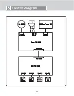
Page 22: ... 22 6 Electric diagram ...
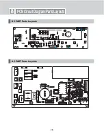
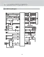
Page 28: ... 28 PCB Circuit Diagram Parts Layouts DC PART Parts Layouts AC PART Parts Layouts 8 ...
Page 29: ... 29 8 PCB Circuit Diagram Parts Layouts DC PART Circuit Diagram ...
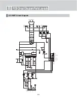
Page 30: ... 30 8 PCB Circuit Diagram Parts Layouts AC PART Circuit Diagram ...
Page 32: ... 33 ...