33
Installation
Due to our policy of continuous product innovation, some specifications may change without notification.
©LG Electronics U.S.A., Inc., Englewood Cliffs, NJ. All rights reserved. “LG” is a registered trademark of LG Corp.
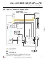
AHU COMMUNICATIONS KIT INSTALLATION
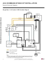
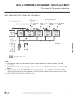
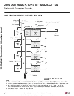
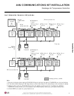
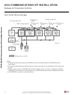
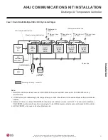
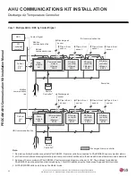
External Connection Diagrams
Multi V + EEV + DDC (Contact Signal)
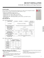
AvailableEEVKitmodels:
-PRLK048A0/PRLK096A0/PRLK396A0
Outdoor unit
EEV Kit
- PRLK594A0 (requires EEV Controller PAEEVA020)
INT(CEN) B
INT(CEN) A
R S T N
Liquid pipe
Gas pipe
Pipe out (Gas)Thermistor
AirHandlingUnit
(field supply)
Pipe in (Liquid)Thermistor
DX
Coil
Fuse
R S TN
Power Supply
DischargeThermistor
1)
Central Controller
ACP : CH5
AC SMART : CH1
A+ B-
Power Supply
L N
Main
module
Comm.
module
ODU Capacity
Control(0~10V)
A+ B-
CH3
A+ B-
CH2
RI2 G
RI3 G RI4 G
Local AHU
Controller
(Field Supplied)
CH 2 A+
On/Off, Cool/Heat,
Emer.stop
CH 2 B-
Adapter
On/Off, Defrost, Alarm,
Comp. status
12V
L
N
EEV
SIG
GND
Remote
Controller
Refrigerant Piping (Field Supply)
Wire & Thermistor (LG Supply)
Wire (Field Supply)
AI/DI/DO Signal(Field Supply)
Note:
1. The type of power supplyofoutdoor unitcan vary depending on the outdoormodel.
2. Please make wiringbetween LGcontroller and outdoorunitwith thesame polarity.
3. LG controller can be optionally applied with DDC.
Fan
c
on
tro
l
IDU
B
IDU
A
Digital
Output
Digital
Input
Universal
Input

