- 31 -
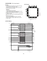
2-1. Description of Control Part
No.
A19~A0
D15~D0
/RD
/WE
IRRCVR0
IRRCVR1
PORTA0
PORTA1
PORTA2
PORTA3
PORTA4
PORTA5
PORTA6
PORTA7
PORTB0
PORTB1
PORTB2
PORTB3
PORTB4
PORTB5
PORTB6
PORTB7
CS0
CS1
EXTINT0
EXTINT1
PA
0
PA
1
PA
2
PA
3
PA
4
PA
5
PA
6
PA
7
PB
0
PB
1
PB
2
PB
3
PB
4
PB
5
IRRCVR0
IRRCVR1
SDA
SCL
NC
E_SDA
E_SCL
SDA_2
SCL_2
N.C
SCDT
N.C
TEMP_DET
LAMP_ON_DET
CASE_DET
PC_SEL2
WP
N.C
8255_CS
N.C
N.C
N.C
N.C
LAMP_ON
FAN_ON
POWER_ON
PC-VIDEO-SEL
PC_SEL1
ADDOWN
TMDSOE
FAN2_DET
KEY_IN1
V_480IP_DET
LAMP_DET
KEY_IN2
FAN_DET
O
I/O
O
O
I
I
O
O
I/O
O
O
O
O
I/O
I
I/O
I
I
I
O
I/O
I/O
O
I/O
I/O
I/O
I/O
O
O
O
O
O
O
O
I
I
I
I
I
I
L
L
H/L
H/L
H/L
H/L
H/L
H/L
H/L
H/L
H
H/L
H
H
H
H/L
H/L
H/L
L
H/L
H/L
H/L
H/L
H
H
H
L
H
H
L
L
L
7
Address Bus
7
Data Bus
7
Read Enable
7
Write Enable
7
Remote Control IR Signal : IR is NEC Format
Not Used
7
I
2
C Bus Clock & Data Line
7
AD9884, FLI2200, VPC3230D, CXA2101
Not Used
7
EEPROM I
2
C Bus Data Line (EEPROM,24LC256)
7
EEPROM I
2
C Bus Clock Line (EEPROM,24LC256)
7
LED Control I
2
C Bus Data Line (M62320)
7
LED Control I
2
C Bus Clock Line (M62320)
Not Connection
7
Sync detection from TFP401.
Not Connection
7
Temperature detect
7
Lamp On/Off status detect.
7
Lamp case open error detect.
7
Selection between RGB3 and RGB1,2 selection result.
7
EEPROM(24LC256)Write protection
Not Connection
7
MSM82C55A Chip Select(for IC Control using data bus)
Not Connection
Not Connection
Not Connection
Not Connection
7
Lamp ON/OFF (HIGH/LOW)
7
Fan ON/OFF (HIGH/LOW)
7
Main Power ON/OFF (HIGH/LOW)
7
Select PC or AV(From CXA1201) for AD9884 input.
7
Select between RGB1 or RGB2.
7
ADC(AD9884) power down for digital RGB3.
7
TFP401 digital RGB output enable for digital RGB3.
7
Fan2 operation error detect(High:fan error)
7
Inputs for KEY Scanning
7
Detect component input(480i or higher resolution->low:480i)
7
Lamp on/off status detect.(High:lamp error)
7
Inputs for KEY Scanning
7
FAN1 operation error detect.
Symbol
I/O
Active
Reset
Function


