background image

4

SAFETY INSTRUCTIONS

15. Lightning 
For added protection for this product (receiver) during a lightning
storm, or when it is left unattended and unused for long periods
of time, unplug it from the wall outlet and disconnect the anten-
na or cable system. This will prevent damage to the product due
to lightning and power-line surges.
16. Power Lines
An outside antenna system should not be located in the vicinity
of overhead power lines or other electric light or power circuits,
or where it can fall into such power lines or circuits. When
installing an outside antenna system, extreme care should be
taken to keep from touching such power lines or circuits as con-
tact with them might be fatal.
17. Overloading
Do not overload wall outlets and extension cords as this can
result in a risk of fire or electric shock.
18. Object and Liquid Entry
Never push objects of any kind into this product through open-
ings as they may touch dangerous voltage points or short-out
parts that could result in a fire or electric shock. Never spill liquid
of any kind on the product.
19. Servicing
Do not attempt to service this product yourself as opening or
removing covers may expose you to dangerous voltage or other
hazards. Refer all servicing to qualified service personnel.
20. Damage Requiring Service
Unplug this product from the wall outlet and refer servicing to
qualified service personnel under the following conditions:

a. If the power-supply cord or plug is damaged.
b. If liquid has been spilled, or objects have fallen into the prod-

uct.

c. If the product has been exposed to rain or water.
d. If the product does not operate normally by following the

operating instructions. Adjust only those controls that are
covered by the operating instructions as an improper adjust-
ment of other controls may result in damage and will often
require extensive work by a qualified technician to restore
the product to its normal operation.

e. If the product has been dropped or the cabinet has been

damaged.

f.

If the product exhibits a distinct change in performance.

18. Object and Liquid Entry
Never push objects of any kind into this product through open-
ings as they may touch dangerous voltage points or short-out
parts that could result in a fire or electric shock. Never spill liquid
of any kind on the product.

19. Servicing
Do not attempt to service this product yourself as opening or
removing covers may expose you to dangerous voltage or other
hazards. Refer all servicing to qualified service personnel.
20. Damage Requiring Service
Unplug this product from the wall outlet and refer servicing to
qualified service personnel under the following conditions:

a. If the power-supply cord or plug is damaged.
b. If liquid has been spilled, or objects have fallen into the prod-

uct.

c. If the product has been exposed to rain or water.
d. If the product does not operate normally by following the

operating instructions. Adjust only those controls that are
covered by the operating instructions as an improper adjust-
ment of other controls may result in damage and will often
require extensive work by a qualified technician to restore
the product to its normal operation.

e. If the product has been dropped or the cabinet has been

damaged.

f.

If the product exhibits a distinct change in performance.

21. Replacement Parts
When replacement parts are required, be sure the service tech-
nician has used replacement parts specified by the manufactur-
er or have the same characteristics as the original part.
Unauthorized substitutions may result in fire, electric shock, or
other hazards.
22. Safety Check
Upon completion of any service or repairs to this product, ask
the service technician to perform safety checks to determine that
the product is in proper operating condition.

23. Wall or Ceiling Mounting
The product should be mounted to a wall or ceiling only as rec-
ommended by the manufacturer. The product may slide or fall,
causing serious injury to a child or adult, and serious damage to
the product.

24. Heat
The product should be situated away from heat sources such as
radiators, heat registers, stoves, or other products (including
amplifiers) that produce heat.

(Continued from previous page)

The explanation about colored dots may be present on PDP screen

The PDP which is the display device of this product is composed of 0.9 to 2.2 million cells and a few cell defects can
occur in the manufacture of the PDP. Several colored dots visible on the screen would be acceptable, in line with other
PDP manufacturers and would not mean that the PDP is faulty. We hope you will understand that the product which cor-
responds to this standard is regarded as acceptable. It means that it could not be changed or refunded.
We promise that we'll do our best to develop our technology to minimize the cell defects.

Summary of Contents for MU-40PA15

Page 1: ...for future reference Record model number and serial number of the Monitor See the label attached on the back of the Monitor and quote this information to your dealer when you require service Model number Serial number MODEL MU 40PA15 MU 40PA15A MU 40PA15B MU 40PA15G MU 40PA15K MU 40PA15S P NO 3828VA0355A NP00KC ...

Page 2: ...ainst harmful interference in a residential installation This equipment generates uses and can radiate radio frequency energy and if not installed and used in accordance with the instructions may cause harmful interference to radio communications However there is no guarantee that interference will not occur in a particular instal lation If this equipment does cause harmful interference to radio o...

Page 3: ...cabinet are provided for ventilation and to ensure reliable operation of the product and to protect it from overheating and these openings must not be blocked or covered The openings should never be blocked by placing the product on a bed sofa rug or other similar surface This prod uct should not be placed in a built in installation such as a book case or rack unless proper ventilation is provided...

Page 4: ...roduct 19 Servicing Do not attempt to service this product yourself as opening or removing covers may expose you to dangerous voltage or other hazards Refer all servicing to qualified service personnel 20 Damage Requiring Service Unplug this product from the wall outlet and refer servicing to qualified service personnel under the following conditions a If the power supply cord or plug is damaged b...

Page 5: ...13 Adjusting Auto Color Control 13 Manual Color Temperature Control 13 Manual Picture Control 13 Audio Menu Options SSM Sound Status Memory 14 AVL Auto Volume Leveler 14 Adjusting Sound Manual Settings 14 Special Menu Options Setting Picture Format 15 Screen Adjustments 15 Auto Adjustments 15 Adjusting Horizontal Vertical Position 16 Adjusting Phase 16 Orbiter 16 White Wash 17 Adjusting OSD Transp...

Page 6: ...LECT ON OFF INPUT VOLUME SELECT Main Power Button Input Select Button Remote Control Sensor Power Standby Indicator Illuminates red in standby Illuminates green when the Monitor is turned on Power Button Volume F G Button Front Panel Controls ...

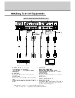
Page 7: ...video out from external equipment to these jacks S VIDEO JACKS Connect video out from an S VIDEO VCR to the S VIDEO input COMPONENT 480i 480p 720p 1080i DVD DTV INPUT JACKS 3 AUDIO INPUT RGB PC INPUT VGA SVGA RGB DTV INPUT 480p 720p 1080i Jacks Connect the monitor output jack of the PC or Digital set top box to this jack REMOTE CONTROL Connect your wired remote control to remote control jack of th...

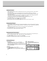
Page 8: ...ent See external equipment operating guide After subscribing to a cable TV service from a local provider and installing a converter you can watch cable TV program ming This monitor cannot display TV programming without a TV tuner device or cable TV converter box connected to the monitor For further information regarding cable TV service contact your local cable TV service provider s 1 Press INPUT ...

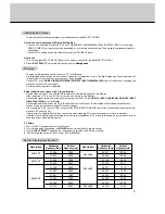
Page 9: ... case adjust contrast or bright ness level to get better picture quality PC Setup 1 Turn on the PC and apply power to the Monitor 2 Turn on the display by pressing the POWER button on the Monitor s remote control 3 Use the INPUT SELECT button on the remote control to select the RGB input source 3 Set the resolution output of the PC under SVGA 800x600 Resolution 640x350 640x400 640x480 Horizontal F...

Page 10: ...r the sub picture MENU Displays on screen menus one by one VCR BUTTONS Controls a LG video cassette recorder OK D E Selects a menu option F G Volume button Increases decreases sound level Adjusts menu settings INPUT SELECT Selects Video S Video Component or RGB mode SSM To select the sound appropriate to your viewing program character Flat Speech Movie Music or User Refer to p 14 STILL Freezes mot...

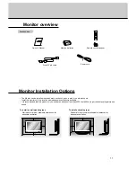
Page 11: ... on a wall or on a desktop etc Install this monitor only in a location where adequate ventilation is available It is recommended that this product only be used at an altitude of less than 5250 feet 1600m to get the best quality picture and sound 4inch 4inch 2 36inch 4inch 1 18inch 4inch 4inch 4inch 4inch 1 18inch To install as wall mounting type Wall mount minimum allowable clearances for adequate...

Page 12: ...ss the INPUT SELECT button on the Monitor or press the POWER INPUT SELECT button on the remote control and then the Monitor will be switched on 1 If the Monitor is turned off with the ON OFF button on the Monitor Press the ON OFF button on the Monitor to turn on the Monitor 2 If the Monitor is turned off with the remote control and also the ON OFF button on the Monitor Press the ON OFF button on t...

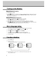
Page 13: ...ou should be adjust colour temperature in PC mode again although color temperature is adjusted in other input source To initialize adjusted value select 0 in Red Green and Blue 1 Press the MENU button and then use D E button to select the menu 2 Press the G button and then use D E button to select the Colour Temp 3 Press the G button and then use D E button to select a color 4 Press the G button a...

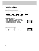
Page 14: ... special adjustment because the Monitor automatically selects the appropriate sound option based on the program content This feature maintains an equal volume level even if you change channels 1 Press the MENU button and then use D E button to select the menu 2 Press the G button and then use D E button to select AVL 3 Press the G button and then use D E button to select On or Off 4 Press the MENU...

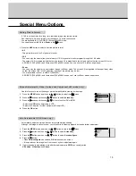
Page 15: ...tton and then use D E button to select the menu 2 Press the G button and then use D E button to select Screen adj 3 Press the G button and then use D E button to to select TV or VCR Select the VCR option if watching a VCR Select the TV option for other equipment Except VCR 4 Press the OK button Automatically adjusts picture position and minimizes image shaking Although the image is still not corre...

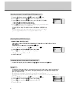
Page 16: ...se 3 Press the G button and then use F G button to adjust phase The adjustment range of Phase is 0 63 4 Press the OK button Avoid keeping a fixed image remain on the Monitor s screen for a long period of time A frozen still picture from a PC video game set displayed on the screen for prolonged periods will result in an image ghost remaining even when you change the image To avoid a permanent image...

Page 17: ...r Temp G 5 Transparency White Wash removes permanent images from the screen Set White Wash On until fixed image disappears 1 Press the MENU button and then use D E button to select the menu 2 Press the G button and then use D E button to select White Wash 3 Press the G button and then use D E button to select On or Off When you select ON the screen changes to white 4 Press the OK button Language G...

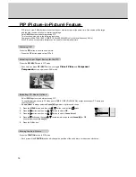
Page 18: ...utton you toggle Video S Video and Component Component source only works in 480i mode Select RGB input source before pressing PIP To use this function connect PC video port to RGB PC INPUT VGA SVGA socket and connect PC audio port to AUDIO INPUT Sound Select is always selected Sound M regardless of prior sound choice 1 Press the MENU button and then use D E button to select the menu 2 Press the G ...

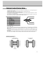
Page 19: ... able to use the remote control and Monitor front panel controls With the RS 232 input connected the Monitor cannot be controlled by both an external control device and the remote con trol at the same time The Monitor can only be controlled by either the remote control or the external control device External Control Device Setup Connect the RS 232C input jack to an external control device such as ...

Page 20: ... PIP position k q 00 03 17 Treble k r 00 64 18 Bass k s 00 64 19 Balance k t 00 64 20 Color temperature k u 00 03 21 R adjustment k v 00 64 22 Green adjustment k w 00 64 23 Blue adjustment k 00 64 24 PIP input source k y 00 03 The Monitor transmits ACK acknowledgement based on this format when receiving normal data At this time if the data is data read mode it indicates present status data If the ...

Page 21: ... select Command b Main picture input G To select input source for the Monitor You can also select an input source using the INPUT SELECT button on the Monitor s remote control Transmission Data 0 RGB 1 Component 2 Video 3 S Video Data 0 RGB 1 Component 2 Video 3 S Video k b Set ID Data Cr Acknowledgement b Set ID OK Data x 01 Power Command a G To control Power On Off of the Monitor Transmission Da...

Page 22: ...ping 2 0 10 5 9 A 8 2D 1 32 0 37 1 5F 9 64 10 09 Color Command i G To adjust the screen color You can also adjust color in the Video menu Transmission Data Min 00 Max 64 Refer to Real data mapping1 as shown below k i Set ID Data Cr Acknowledgement Data Min 00 Max 64 i Set ID OK Data x 10 Tint Command j G To adjust the screen tint You can also adjust tint in the Video menu Transmission Data Red 00 ...

Page 23: ...ol 2 Warm 3 User k u Set ID Data Cr Acknowledgement u Set ID OK Data x 16 PIP Position Command q G To select sub picture position for PIP You can also adjust the sub picture position using the POSITION on the remote control or in the Special menu Transmission Data 0 Right down on screen 1 Left down on screen 2 Left up on screen 3 Right up on screen k q Set ID Data Cr Acknowledgement Data 0 Right d...

Page 24: ... to Real data mapping2 See page 22 Data Min 00 Max 64 k v Set ID Data Cr Acknowledgement v Set ID OK Data x 22 Green Adjustment Command w G To adjust green in green temperature Transmission Data Min 00 Max 64 Refer to Real data mapping2 See page 22 Data Min 00 Max 64 k w Set ID Data Cr Acknowledgement w Set ID OK Data x 23 Blue Adjustment Command G To adjust blue in green temperature Transmission ...

Page 25: ...ode G Lead code 1st flame Low custom code Lead code High custom code Data code Data code TC Tf T1 C0 Carrier frequency FCAR 1 TC fOSC 12 Duty ratio T1 TC 1 3 Repeat flame C1 C2 C3 C4 C5 C6 C7 C0 C1 C2 C3 C4 C5 C6 C7 D0 D1 D2 D3 D4 D5 D6 D7 D0 D1 D2 D3 D4 D5 D6 D7 Repeat code 9 ms 4 5 ms 0 55 ms 9 ms 2 25 ms How to connect How to connect Remote Control IR Code NEC Format Remote Control IR Code NEC ...

Page 26: ... On Off Discrete Only Power On Discrete Only System Off R C Button R C Button Discrete Input RGB Power On Discrete Input VIDEO Power On Discrete Input S VIDEO Power On Discrete Input COMPONENT Power On R C Button R C Button R C Button R C Button R C Button R C Button R C Button R C Button R C Button R C Button Discrete Only 16 9 mode Discrete Only 4 3 mode Discrete Only ZOOM mode Code Hexa Functio...

Page 27: ...t with a soft dry lint free cloth Please be sure not to use a wet cloth If you leave your Monitor dormant for a long time such as a vacation it s a good idea to unplug the power cord to protect against possible damage from lightning or power surges Early malfunctions can be prevented Careful and regular cleaning can extend the amount of time you will have your new Monitor Be sure to turn the power...

Page 28: ...or Poor picture Select Colour in the VIDEO menu and press the VOLUME G but ton Refer to p 13 Keep a certain distance between the Monitor and the VCR Activate any function to restore the brightness of the picture If still picture is on the screen for more than 5 minutes the screen gets dark The remote control doesn t work Check to see if there is any object between the Plasma Display and the remote...

Page 29: ...29 Note ...

Page 30: ...30 Note ...

Page 31: ...ches Depth inches Weight pounds Power requirement Resolution Color 16 770 000 256 steps of each R G and B 36 6 28 3 1 71 8 640 x 480 Dot This product specifications above can be changed without notice for quality improvement MU 40PA15 B G K S AC 120V 60Hz ...

Reviews: