1
10-2
CHECKING FLOW CHART BY FAILURE
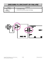
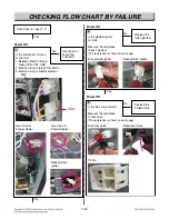
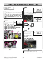
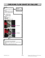
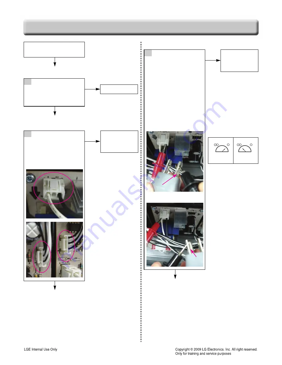
Power Failed(Dead),
No display?
Go to No 4
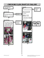
Power On State
Check the key beep. Touch
the “clear key”, Is the beep
sound?
No
Yes
Yes
2
Reconnect or
repair the
connector
Replace the
defective
harness
Power Off State
Is the connector connected
to Power PCB disconnected
or disassembled? (CN1),
between Power PCB (CN10)
and display PCB(CN9)
No
Yes
Power Off
CN1
CN1
CN1
CN1
CN1
CN1
CN1
CN1
CN1
CN1
CN1
CN1
CN1
CN1
CN1
CN1
CN1
CN1
CN1
CN1
CN1
CN1
CN10
CN10
CN10
CN10
CN10
CN10
CN10
CN10
CN10
CN10
CN10
CN10
CN10
CN10
CN10
CN10
CN10
CN10
CN10
CN10
CN10
CN10
CN9
CN9
CN9
CN9
CN9
CN9
CN9
CN9
CN9
CN9
CN9
CN9
CN9
CN9
CN9
CN9
CN9
CN9
CN9
CN9
CN9
CN9
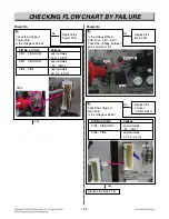
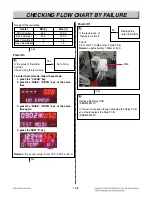
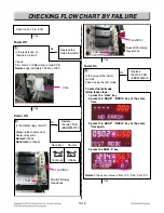
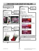
3
Is the electric wiring normal?
Measure the resistance
Power cord and CN01’s
connection
Normal
: continuity
Abnormal
: infinite
- Code L to Pin3 of CN01(BK)
- Code N to Pin1 of CN01(WH)
BK color is L.
White color is N
Yes
No
L
L
L
L
L
L
L
L
L
L
L
L
L
L
L
L
L
L
N
N
N
N
N
N
N
N
N
N
N
N
N
N
N
N
N
N
Normal
Abnormal
Continuity
Infinite
Summary of Contents for LSRG309ST
Page 77: ......


