background image

6-1

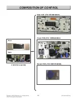
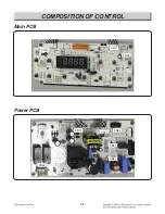
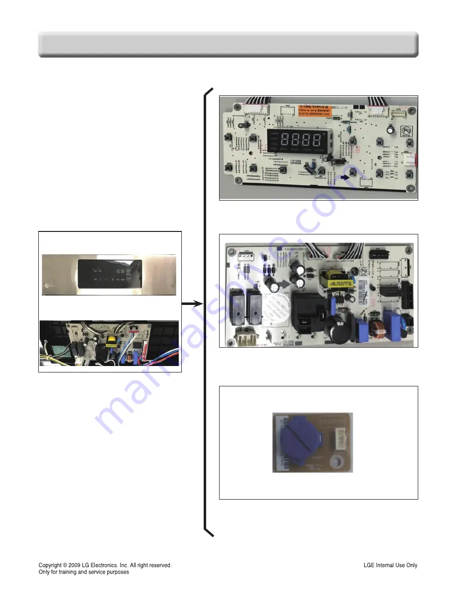
COMPOSITION OF CONTROL

Front

Back

Controller assembly

Main PCB  (P/N : EBR82400801)

Power PCB (P/N : EBR82400901)

Buzzer PCB ( P/N : EBR76332902)

Summary of Contents for LRG3060ST

Page 1: ...30 Freestanding Gas Range SERVICE MANUAL MODEL LRG3060ST CAUTION BEFORE SERVICING THE UNIT READ THE SAFETY PRECAUTIONS IN THIS MANUAL P NO MFL38379755 August 2018 Printed in Korea Internal Use Only ...

Page 2: ...side of warming drawer The power supply of the appliance should be turned off when it is being repaired FORWARD LG Electronics assumes no responsibility for any repairs made on our products by anyone other than Authorized Service Technicians WARNING DISCONNECT power supply cord from the outlet before servicing Replace all panels and parts before operating RECONNECT all grounding devices Failure to...

Page 3: ...s 3 1 Removing the Back Control cover and Key pad assembly 3 2 Removiing Power Control Board PCB 3 3 Removiing the Cooktop Plate and the Spark Module 3 4 Removing the Case assembly Cooktop Burner assembly 3 5 Removing the Cooktop Parts 3 6 3 7 Removing the BROIL Burner assembly 3 9 Oven Bottom the Frame guide and the Burner assembly 3 10 Removing the Oven light Socket assembly 3 12 Removing the Ov...

Page 4: ... 2 Power PCB 6 2 DIAGNOSIS THROUGH SCHEMATIC 7 1 CHECK THE FAILURE CODE F code 8 1 FAILURE CODE SUMMARY 9 1 CHECKING FLOW CHART BY FAILURE 10 1 10 22 No display No power 10 1 10 4 No heating including F9 error 10 5 10 8 Sensing fail including F1 F2 error 10 13 10 16 Oven hot including F6 error 10 17 10 19 No Key input 10 20 Oven lamp does not operate 10 21 10 22 TROUBLE SHOOTING 11 1 11 4 EXPLODED...

Page 5: ...ure to do so can result in severe personal injury death or electrical shock DO NOT touch burners grates or interior surfaces of oven Heating element may be hot even though they are off Interior surfaces of an oven become hot enough to cause burns During and after use do not touch or let clothing or other flammable materials contact burners grates or interior surfaces of oven until they have had su...

Page 6: ... other flammable materials contact burners grates or interior surfaces of oven until they have had sufficient time to cool Other surfaces of the appliance may become hot enough to cause burns among these surfaces are oven vent openings and surfaces near these openings oven doors and windows of oven doors WARNING DO NOT store items of interest to children in cabinets above a range or on the back gu...

Page 7: ...urned Inward and Not Extend Over Adjacent Surface Units To reduce the risk of burns ignition of flammable materials and spillage due to unintentional contact with the utensil the handle of a utensil should be positioned so that it is turned inward and does not extend over adjacent surface units Be sure you know which knobs operate each burner Make sure you turned on the correct burner To prevent b...

Page 8: ...1 4 GENERAL The Model Serial Number label and Tech Sheet locations are shown below Model Serial Number Location MODEL SERIAL NUMBER LABEL AND TECH SHEET LOCATIONS Tech Sheet Location On Low Rear Cover ...

Page 9: ... volume Hi Lo Off 5 switch the temperature scale between Fahrenheit and Celsius F C Cooktop Material Enamel of element 5 5 Input Rate NAT LP BTU hr LR 9 1k 9 1k RR 5k 5k CR 8k 8k LF 12k 9 5k RF 17k 10k Oven Capacity cu fe 5 4 Broil NAT LP BTU hr 15 5k 12 5k Bake BTU hr 19k 18k Convection system Yes of Racks 2 standard Interior oven light auto manual Proof No Cook warm No Favorites No Door lock out...

Page 10: ...ode Bake burner operates during bake mode Bake can be used to cook foods which are normally baked Oven must be preheated Broil Mode Broil burner operates during broil mode Broil can be used to cook foods which are normally broiled Preheating is not required when using broil All foods should be turned at least once except fish which does not need to be turned Cooking Guide Refer to the owners manua...

Page 11: ...I or LO broil 9 Clock Press and then use the and buttons to set the time of day 10 Setting Press the Settings key repeatedly to toggle through and change oven settings 11 CLEAR OFF Lockout Press to cancel all oven operations except the clock and timer Press and hold the button for 3 seconds to activate deactivate the oven Lockout function NOTE If F and a number appear in the display and the oven c...

Page 12: ...e oven light automatically turns ON when the door is opened The oven light may also be manually turned ON or OFF by press the OVEN LIGHT pad 5 TIMER ON OFF To cancel timer at any time touch TIMER ON OFF pad Note 1 If you press Timer On Off button once to set the time in hours and minutes or press the button twice to set the time in minutes and seconds TIMER flashes in the display 2 If Timer On Off...

Page 13: ...and hold the Clear Off button for three seconds A melody sounds and LOCKED in the display 2 To deactivate the Lockout feature press and hold the Clear Off button for three seconds BAKE Desired temperature START COOK TIME Desired time START START BROIL once High twice Low ...

Page 14: ...S 1 800 243 0000 LG Canada 1 888 542 2623 2 When instructed to do so by the call center agent hold the mouthpiece of your phone over the Smart Diagnosis logo on the machine Hold the phone no more than one inch from but not pressing the machine 3 Press and hold the Start button for three seconds 4 Keep the phone in place until the tone transmission has finished This takes about 6 seconds and the di...

Page 15: ...nge The components and their locations are shown below COMPONENT LOCATIONS Oven valve Gas pressure regulator Main Power PCB Burner body Cooktop valve Bake burner Ignition switch Door lock assembly Broil burner Burner pipe Igniter broil Oven light Oven sensor Igniter bake Door switch Spark module ...

Page 16: ...ve the eyebrow 9 Remove the 4 screws of controller sub assembly 10 Pull the controller sub assembly and lift it up from the supporters 11 Remove the 3 screws of controller sub assembly 12 Replace the key pad assembly 7 Remove the 2 screws of PCB assembly and separate PCB assembly after unpluging the connectors REMOVING THE BACK CONTROL COVER AND KEY PAD ASSEMBLY WARNING DISCONNECT power supply cor...

Page 17: ...e proper pcb in default mode and check main pcb NOTE Refer to the page 6 1 6 2 for composition of control board Main Power PCB WARNING DISCONNECT power supply cord from the outlet before servicing Replace all panels and parts before operating RECONNECT all grounding devices Failure to do so can result in severe personal injury death or electrical shock CAUTION Be careful when you work on the gas r...

Page 18: ... the front clips line up the burner body and with the cooktop to replace screws 6 5 connectors of the electrode and a connector of the harness a Disconnect 6 connectors b Remove the 2 screws c Remove the 2 tabs by using long nose pliers REMOVING THE COOKTOP PLATE AND THE SPARK MODULE WARNING DISCONNECT power supply cord from the outlet before servicing Replace all panels and parts before operating...

Page 19: ...emove 2 phillips head screws REMOVING THE CASE ASSEMBLY COOKTOP BURNER ASSEMBLY WARNING DISCONNECT power supply cord from the outlet before servicing Replace all panels and parts before operating RECONNECT all grounding devices Failure to do so can result in severe personal injury death or electrical shock 2 screws 2 screws 2 screws 2 screws 2 screws 2 screws 2 screws 2 screws 2 screws 2 screws 2 ...

Page 20: ...is designated 1 Turn off the electrical supply and gas supply going to the range 2 Remove the cooktop plate See REMOVING THE COOKTOP PLATE on page 3 4 1 screw 1 screw 1 screw 1 screw 1 screw 1 screw 1 screw 1 screw 1 screw 1 screw 1 screw 1 screw 1 screw 1 screw 1 screw 1 screw 1 screw 1 screw 1 screw 1 screw 1 screw 1 screw 1 screw 1 screw 1 screw 1 screw 1 screw 1 screw 1 screw 1 screw 1 screw 1...

Page 21: ...on page 3 5 b Pry on the 2 release tabs and slide the switch off the valve stem c Remove the 2 connectors and remove the ignition switch 5 To remove the electrode spark plug a Remove the connector from the spark module b Stretch the electrode bracket c Remove the electrode from the burner housing ...

Page 22: ... the outlet before servicing Replace all panels and parts before operating RECONNECT all grounding devices Failure to do so can result in severe personal injury death or electrical shock CAUTION Be careful when you work on the gas range handling the sheet metal part Sharp edge may be present and you can cut yourself 1 Turn off the electrical supply and gas supply going to the range 2 Open the oven...

Page 23: ...bly 4 To remove the igniter a Perform step 1 3 on this page b Remove the 2 screws and then remove the igniter b 3 b 2 b 1 b 5 b 4 WARNING DISCONNECT power supply cord from the outlet before servicing Replace all panels and parts before operating RECONNECT all grounding devices Failure to do so can result in severe personal injury death or electrical shock Make sure the igniter connecter is complet...

Page 24: ...iter OVEN BOTTOM THE FRAME GUIDE AND THE BURNER ASSEMBLY Igniter plug 2 screws 2 screws 2 screws 2 screws 2 screws 2 screws 2 screws 2 screws 2 screws 2 screws 2 screws 2 screws 2 screws 2 screws 2 screws 2 screws 2 screws 2 screws 2 screws 2 screws 2 screws 2 screws 2 screws 2 screws 2 screws 2 screws 2 screws 2 screws 2 screws 2 screws 2 screws 2 screws 2 screws 2 screws 2 screws 2 screws 4 scre...

Page 25: ...s Socket Clips Socket Clips Socket Clips Socket Clips Socket Clips Socket Clips Socket Clips Socket Clips Socket Clips Socket Clips Socket Clips Socket Clips Socket Clips Socket Clips Socket Clips Socket Clips Socket Clips Socket Clips Socket Clips Socket Clips Socket Clips Socket Clips Socket Clips Socket Clips Socket Clips Socket Clips Socket Clips Socket Clips Socket Clips Viewed From Rear Pane...

Page 26: ... sensor WARNING DISCONNECT power supply cord from the outlet before servicing Replace all panels and parts before operating RECONNECT all grounding devices Failure to do so can result in severe personal injury death or electrical shock CAUTION Be careful when you work on the gas range handling the sheet metal part Sharp edge may be present and you can cut yourself 2 screws 2 screws 2 screws 2 scre...

Page 27: ...lace the two screws REMOVIING REPLACING THE DRAWER CAUTION Disconnect the electrical power to the range at the main fuse or circuit breaker panel Failure to do so can result in severe personal injury death or electrical shock CAUTION DO NOT touch interior surfaces of oven between door and drawer During and after use do not touch interior surfaces of oven between door and drawer until they have had...

Page 28: ...n door To remove the door 1 Fully open the door 2 Pull the hinge locks up toward Fig 1 the door frame to the unlocked position 3 Firmly grasp both sides of the door at the top 4 Close door to the door removal position which is approximately 5 degrees refer to the Fig 2 5 Lift door up and out until the hinge arm is clear of the slot Slot Hinge lock Lock Unlock Hinge arm Indentation Bottom edge of s...

Page 29: ...emove the door handle trim a Remove the 2 door handle screws and lift the door handle off door trim and slide up the door trim 4 top liner screws Door handle screw 3 bottom liner screws Door handle screw WARNING DISCONNECT power supply cord from the outlet before servicing Replace all panels and parts before operating RECONNECT all grounding devices Failure to do so can result in severe personal i...

Page 30: ...ge hanger out of the door liner slot 8 To remove the oven door glass assembly a Remove the 8 screws b Lift the insulation cover off the door liner d Lift the inner oven door glass and bracket assembly out of the door liner REASSEMBLY NOTE When you reinstall the insulation around the oven door glass make sure that the insulation is not visible in the glass after the door is reassembled Hinge hanger...

Page 31: ...ket out of the liner holes Door gasket Gasket clip Liner Hole WARNING DISCONNECT power supply cord from the outlet before servicing Replace all panels and parts before operating RECONNECT all grounding devices Failure to do so can result in severe personal injury death or electrical shock CAUTION Be careful when you work on the gas range handling the sheet metal part Sharp edge may be present and ...

Page 32: ... from the wall so you can access the back of the unit 4 Remove the rear panel see page 3 2 5 Raise the cooktop plate see the page 3 4 for the procedure 6 Remove the two screws from the top rear of the side panel WARNING DISCONNECT power supply cord from the outlet before servicing Replace all panels and parts before operating RECONNECT all grounding devices Failure to do so can result in severe pe...

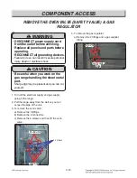
Page 33: ...ift the oven valve 4 To remove the gas regulator a Remove the 2 fittings and a gas supplier fitting WARNING DISCONNECT power supply cord from the outlet before servicing Replace all panels and parts before operating RECONNECT all grounding devices Failure to do so can result in severe personal injury death or electrical shock CAUTION Be careful when you work on the gas range handling the sheet met...

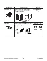
Page 34: ...wer cord unplugged from outlet and with wiring harness or connectors disconnected Before testing any of components perform the following checks WARNING Turn off the electrical supply and gas supply going to the range Replace all panels and parts before operating Reconnect all grounding devices after servicing Failure to do so can result in death or electrical shock NOTE Below Ω value were tested a...

Page 35: ...1 Door open Door closed Oven lamp 1 Measure the resistance after cooling down Multiple meter scale R x1 Normal Approximately 5 Ω 10 If not replace Broil or bake igniter 1 Refer to page 3 9 3 10 for servicing procedure 2 Measure the resistance after cooling down Multiple meter scale R x 1 Normal 45 Ω 400 Ω Room Temperature Resistance If not replace Continuity Infinite ...

Page 36: ...istance after cooling down Multiple meter scale R x 1 Normal Approximately 1 3 Ω If not replace Ignition switch 1 Refer to page 3 6 3 7 for servicing procedure 2 Measure the resistance by rotating the cam of each switch slowly Multiple meter scale R x 1 approximately 40 80 other Infinite Continuity Upside Downside 40 80 ...

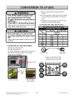
Page 37: ...careful when you work on the gas range handling the sheet metal part Sharp edge may be present and you can cut yourself CAUTION If the gas supply to the range is disconnected for any reason see the installation instructions for proper connection and safety precautions 2 CONVERT THE PRESSURE REGULATOR Pull the range away from the wall and the pressure regulator is located at the rear of the range 3...

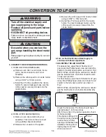
Page 38: ... WARNING Turn off the electrical supply and gas supply going to the range Replace all panels and parts before operating RECONNECT all grounding devices Failure to do so can result in severe personal injury death or electrical shock CAUTION Be careful when you work on the gas range handling the sheet metal part Sharp edge may be present and you can cut yourself 4 CONVERTING THE SURFACE BURNERS Remo...

Page 39: ...g Insert the choke into the burner base then insert the set screw into the burner base and tighten securely Make sure the screw head is against the shoulder within choke notch so it does not have any rotational movement 6 Put the old orifice spuds into conversion kits and place back on the range for possible future conversion NOTE If an orifice spud is accidentally dropped the cooktop plate can be...

Page 40: ...ce spud F to the nozzle holder To prevent leakage make sure the orifice spud is securely screwed into the nozzle holder 6 Turn on the Electrical and Gas Supply to continue with flame adjustment 7 ADJUSTING THE AIR SHUTTER For bake burner adjust the Air Shutter for LP gas loosen the Phillips head screw and rotate the shutter to the fully open position as shown in Fig 1 NOTE When converting the unit...

Page 41: ... appliance to the original gas NOTE The choke for the 17k top burner must be removed when converting the range back to natural gas WARNING Turn off the electrical supply and gas supply going to the range Replace all panels and parts before operating RECONNECT all grounding devices Failure to do so can result in severe personal injury death or electrical shock CAUTION Be careful when you work on th...

Page 42: ...6 1 Composition of control Front Back Controller assembly Main PCB P N EBR82400801 Power PCB P N EBR82400901 Buzzer PCB P N EBR76332902 ...

Page 43: ...6 2 Composition of control Main PCB CN10 CN31 CN51 CN01 CN52 CN11 CN10 CN11 CN20 Power PCB ...

Page 44: ... Sensor resistance approximately 1 06 kΩ at 65F 1 12 kΩ at 85F Symptom Oven lamp not operating Check the Lamp coil s resistance Normal approximately 20 40Ω Symptom no heating F 9 Check related part Check related part Symptom Oven hot F 6 Check All heater relays are open short 3 4 5 ...

Page 45: ... 2 press the BAKE and BROIL key at the same time for 1 second If the oven has some failure the oven will show the failure code like FIG 1 It shows the type of F code and times of occurred failure alternately for each two seconds If the oven does not have any failure the oven will display like FIG 2 NOTE After checking the failure code press the CLEAR key Type of F code FIG 1 FIG 2 Times of the occ...

Page 46: ...4 above B Remove panel and connections on oven sensor Check value at room temperature is should be 1090 Ohms C Check wire continuity D Replace PCB F 9 Bake failure A Perform step 1 through 4 above Also check the gas flame gas pressure B Remove the back panel and check continuity of the sensor heater bake broil and control PCB C Check the oven burner ignition system Refer to oven bumer ignition sys...

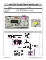
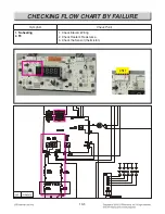
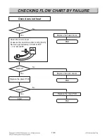
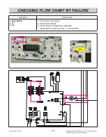
Page 47: ...10 1 CHECKING FLOW CHART BY FAILURE CN11 Symptom Check Point 1 Power Failure Dead 2 No Display 1 Check Electric Wiring 2 Check the Power PCB and Main PCB Voltage ...

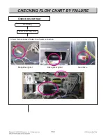
Page 48: ...tage of Power PCB Power PCB CN01 pin1 and pin3 Blank display Enter key input Disconnect the power No No Some beep sounds Oven display blanks Is it 120V AC Normal END 2 3 pin 1 Pin No No Yes Yes Yes Yes CN11 Check the harness of between L1 N Replace the defective harness 1 END ...

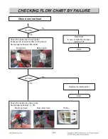
Page 49: ...nce PIN No of CN01 Resistance 1pin 3pin approximately 138 Ω Check the voltage of Power PCB CN13 pin 1 and pin 3 pin1 and pin 4 PIN No of CN11 Voltage PIN1 GND PIN3 PIN1 GND PIN4 approximately 9V approximately 4 5V 5 5V Normal END No Power On Yes Replace the power PCB 2 1 Pin 4 Pin CN01 ...

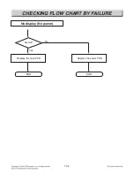
Page 50: ...10 4 CHECKING FLOW CHART BY FAILURE No display No power Yes Normal END No Replace the main PCB END Replace the power PCB ...

Page 51: ...10 5 CHECKING FLOW CHART BY FAILURE CN11 Symptom Check Point 1 No heating 2 F9 1 Check Electric Wiring 2 Check Heater s Resistance 3 Check the Sensor thermistor ...

Page 52: ...10 6 CHECKING FLOW CHART BY FAILURE Oven does not heat Check the looseness of bake broil heater connection Broil globar ignitor Bake globar ignitor Gas Valve No Heating Disconnect the power ...

Page 53: ...easure the resistance after cooling down Normal approximately 45Ω 400Ω Check the resistance of Gas valve Normal approximately 1 1 5Ω Reconnect In case of defective harness replace or fix Normal END No Replace the failed ignitor Baker ignitor Broil ignitor Bake Gas Valve Pin No Broil Gas Valve 1pin WH N 1 4 3 2 3pin ...

Page 54: ...Yes Replace the Failed Valve Check the oven sensor measure the resistance after cooling down Normal approximately 1 06 kΩ at 65F 1 12 kΩ at 85F NO COM Normal END No Yes Replace the oven sensor Normal END END No Yes Replace the main PCB Normal Replace the power PCB ...

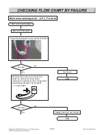
Page 55: ...ING FLOW CHART BY FAILURE CN11 Symptom Check Point 1 Sensing Fail 2 F 1 3 F 2 1 Check the electric wiring 2 Check the test Mode 3 Check the sensor thermistor resistance approximately 1 06 kΩ at 65F 1 12 kΩ at 85F ...

Page 56: ...ensor connector END No Yes Reconnect Disconnect the main oven sensor and check the main oven sensor value measure the resistance after cooling down Normal approximately 1 06 kΩ at 65F 1 12 kΩ at 85F NO COM Normal END No Yes Replace the main oven sensor Normal Main oven sensing failed Disconnect the power ...

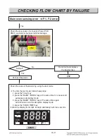
Page 57: ...test mode To enter the test mode follow these steps 1 press the clear key 2 press the BAKE BROIL key at the same time for one second failure code display mode 3 press the BAKE BROIL key at the same time again S W version and model option display mode 4 press the COOK TIME key It show the display from step1 to step3 alternately each two seconds Reconnect and replace the bad harness Connect the powe...

Page 58: ...e sensor value is from 65 F to 95 F at room temp TIMER DELAY TIMED BAKE BROIL WARM CLEAN LOCKED HR TIMER DELAY TIMED BAKE BROIL WARM CLEAN LOCKED HR TIMER DELAY TIMED BAKE BROIL WARM CLEAN LOCKED HR TIMER DELAY TIMED BAKE BROIL WARM CLEAN LOCKED HR STEP 2 STEP 3 END sensor value END No Yes Replace the Power PCB Normal ...

Page 59: ...10 13 CHECKING FLOW CHART BY FAILURE Symptom Check Point 1 Oven hot 2 F 6 1 Check the Resistance of the Relay RY58 RY87 TAB03 ...

Page 60: ...or Check the bake relay damage measure the resistance Normal No END Replace the main oven sensor Welded Normal Continuity Infinite NO COM NO COM Disconnect the power and main oven sensor Check the main oven sensor value measure the resistance after cooling down Normal approximately 1 06 kΩ at 65F 1 12 kΩ at 85F NO COM ...

Page 61: ...RE Oven too hot error F 6 error Normal No END END Replace the power PCB Replace the main PCB Yes Yes Check the broil relay damage measure the resistance Welded Normal Continuity Infinite NO COM NO COM Normal No END Replace the power PCB ...

Page 62: ... lock operation Nomal unlock No key input END END END No No Yes Yes Cancel the Door locking press the start key for three seconds Normal No Yes Replace the control panel Replace the main PCB Normal Normal Check the control panel and Find the mechanical malfunction of key ...

Page 63: ...f oven lamp terminal and harness Check the looseness of connector Power PCB CN01 END No No Yes Normal Yes Normal Oven lamp does not operate Disconnect the power Oven lamp does not operate Reconnect In case of the defective harness replace or fix Reconnect END ...

Page 64: ...n lamp does not operate Yes Normal No Check the oven lamp measure the resistance Normal approximately 20 40Ω Abnormal infinite Replace the oven lamp Replace the power PCB END Yes Normal No Replace the main PCB END END Abnormal Infinite NO COM ...

Page 65: ...off valve may have accidentally been moved during cleaning or moving Place oven rack in center of oven Place a level on the oven rack Adjust leveling legs at base of range until the oven rack is level Be sure floor is level and is strong and stable enough to adequately support range Contact a carpenter to correct the situation Be sure cabinets are square and have sufficient room for range clearanc...

Page 66: ...wn or the circuit breaker tripped Improper oven controls setting The light bulb is loose or defective The plug on range is not completely inserted in the electrical outlet See the OPERATION section in user s guide See the OPERATION section in user s guide See the OPERATION section in user s guide See the Changing Oven Settings section in user s guide See the Changing Oven Settings section in user ...

Page 67: ... outage clock flashes Power outage or surge Reset the clock If the oven was in use you must reset it by touching the pressing Clear Off setting the clock and resetting any cooking function Strong odor An odor from the insulation around the inside of the oven is normal for the first few times the oven is used This is temporary Drawer does not slide smoothly or drags The drawer is out of alignment D...

Page 68: ...EXPLODED VIEW EV INTRODUCTION DOOR PARTS DRAWER PARTS COOKTOP PARTS CONTROLLER PARTS CAVITY PARTS Customer Model MODEL Product Code SVC Model ...

Page 69: ...DOOR PARTS 1704 1704 W243 1000 1009 W222 1020 1703 1733 1733 1703 1018 1015 W101 1021 1045 W225 EV ...

Page 70: ...2381 2037 2036 2033 2136 2006 3006 2029 2048 W227 W158 2501 2028 2128 2382 204A 2044 2043 260B CONTROLLER PARTS EV ...

Page 71: ...3979 3974 W294 3056 W295 3402 3925 2441 3401 3990 3986 3991 3940 3960 3961 3962 3963 3992 3964 3950 3951 3957 3956 3977 3973 3978 3972 W294 3946 3945 3993 3994 3995 W294 3985 3953 3985 3958 3954 3985 3985 3935 3985 3936 3952 3006 3403 3930 ...

Page 72: ...DRAWER PARTS 8025 8025 8512 8502 8508 8502 8507 8501 8514 8513 8513 8388 W228 5505 5505 8504 8520 8519 8511 W229 9381 8541 EV ...

Page 73: ...5505 W230 W231 5511 5539 3006 3006 5515 3501 W290 5900 5922 5911 5904 5943 W231 W231 5912 5921 5903 5700 W231 W231 5952 5958 5463 5010 5505 5014 5019 3013 3924 3006 8550 5539 2041 5931 5409 W231 2058 9384 5517 W401 5462 5955 5905 W231 5464 5944 5942 5941 5900 W231 W115 ...

Page 74: ......

Reviews: