


3-2
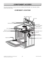
COMPONENT ACCESS
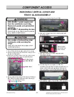
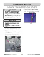
1. Turn off the electrical supply going to the range.
2. Pull the range away from the wall so that you can
access the rear panel.
3. After remove the 8 screws from the control cover,
removing the control cover and label bracket.
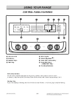
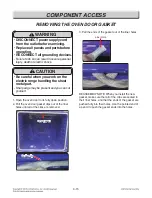
REMOVING CONTROL COVER AND
TOUCH GLASS ASSEMBLY
WARNING
• DISCONNECT power supply cord
from the outlet before servicing.
• Replace all panels and parts before
operating.
• RECONNECT all grounding devices.
- Failure to do so can result in severe personal
injury, death or electric shock.
Control Cover
Label Bracket
Back Cover
CAUTION
• Use caution when handling sheet
metal parts while servicing the
range.
- Some parts may have sharp edges, which
could result in injury.
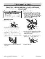
4. Remove Main PCB, Relay PCB, Buzzer PCB and
NFC PCB from PCB Supporter after removing 2
screws and unlocking 9 hooks.
( : Screw / : Hook)
5. Unplug 1 connector from Touch PCB.
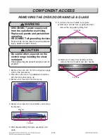
6. Remove 3 screws from front control panel with
small size driver.
Driver height
should be less
than 100mm.
7. Remove bracket from PCB supporter after
removing 3 screws.
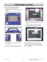
8. For servicing the touch glass or PCB, the
controller sub assembly should be separated as a
whole. And provide sub assembly composed of
the Touch glass, Touch PCB and PCB supporter.
**Sub assembly : Glass + Touch PCB + PCB supporter