4-5
Components
Test procedures
Results
Single surface units:
Left Rear(LR)
Right Rear(RR)
Element
1. Refer to page 3-4 for the servicing procedure
2. Set the Multiple meter scale to the R x 1
3. Disconnect wires from cook-top elements
4. Touch the ohmmeter test leads to the element
terminal and 1A.
The meter should indicate 47 Ω ± 10%
Normal: Approximately 47 Ω,
If not replace
1A
2A
5. Touch the ohmmeter test leads to limiter terminals
1B and 2B.
With the temperature below 150˚F, the meter
should indicate an open circuit(infinite).
With the temperature above 150˚F, the meter
should indicate continuity (0Ω).
Below 150˚F
open circuit(infinite).
Above 150˚F
continuity (0 Ω)
1B
2B
Summary of Contents for LDE4415BD
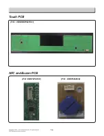
Page 57: ...5 3 Touch PCB P N EBREBR79627601 P N EBR78789101 P N EBR76332902 NFC and Buzzer PCB ...
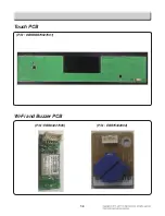
Page 60: ...5 6 Touch PCB P N EBREBR79627601 P N EBR83227505 P N EBR76332902 Wi Fi and Buzzer PCB ...
Page 88: ...8 3 LOWER BAKE CONV BAKE CONV ROAST LOWER BROIL ...
Page 89: ...8 4 UPPER SELFCLEAN LOWER SELFCLEAN ...
Page 90: ...8 5 OVEN LAMP CLOCK DISPLAY ON ...
Page 91: ...8 6 CR Cooktop element LR RR Cooktop element ...
Page 92: ...8 7 LF Cooktop element RF Cooktop element ...
Page 98: ... EV COOKTOP PARTS 3056 3402 3099 3059 330S 330S 3022 330M 330H 3006 3204 3016 301C ...
Page 101: ......


