


5. Trouble shooting
- 98 -
5.12 RF PART TROUBLESHOOTING
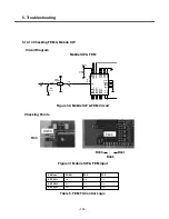
5.12.1 RF Components
Main PCB Top
Main PCB Bottom
U401
FL308
U402
X401
SW401
Figure 1. RF Components Placement
Table 1. RF Components
REFERENCE
PART Description
U401
PAM (Power Ampilifier Module)
X401
VCTCXO (26MHz)
FL308
FEM (Front End Module)
U402
Transceiver
SW401
Mobile Switch
Summary of Contents for KE820
Page 1: ...Service Manual Model KE820 Service Manual KE820 Date August 2006 Issue 1 0 ...
Page 3: ... 4 ...
Page 5: ... 6 ...
Page 46: ...3 TECHNICAL BRIEF 47 Figure 18 EN SET port control method ...
Page 69: ...4 PCB layout 70 Figure 45 Main PCB bottom Figure 46 Main PCB bottom placement ...
Page 70: ...4 PCB layout 71 Figure 47 Sub PCB top Figure 48 Sub PCB top placement ...
Page 71: ...4 PCB layout 72 Figure 49 Sub PCB bottom Figure 50 Sub PCB bottom placement ...
Page 114: ...6 Download S W upgrade 115 6 2 Download program user guide ...
Page 115: ... 116 6 Download S W upgrade ...
Page 116: ... 117 6 Download S W upgrade ...
Page 117: ... 118 6 Download S W upgrade ...
Page 124: ... 125 8 PCB LAYOUT ...
Page 125: ... 126 8 PCB LAYOUT ...
Page 126: ... 127 8 PCB LAYOUT ...
Page 127: ... 128 8 PCB LAYOUT ...
Page 141: ... 142 ...
Page 161: ...Note ...
Page 162: ...Note ...


