5. Trouble shooting
- 101 -
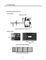
5.12.4 Checking PLL Control signals
Checking Points
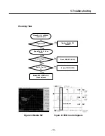
Checking Flow
Circuit Diagram
RF Transceiver
Waveform
Figure 7. Transceiver
Figure 8. Transceiver Circuit
Figure 9. PLL Control Waveform
C430
22p
R427
0
C422
0.1u
X401
GND
2
3
OUT
VCC
4
VCONT
1
26MHz
C418
0.1u
R425
2V7_VCXO
0
R419
C431
1uF
47n
C419
R426
0
R424
0
R448
0
C421
0.1u
100p
C426
R414
820
VCO_RC
18
31
VDDBIAS2V8
8
VDDDIG1V5
VDDDIG2V8
5
21
VDDLNA1V5
X2V8
VDDRX1V5
19
20
VDDRX2V8
X1V5
X2V8
VDDVCO2V8
17
VDDXO2V8
15
XO
11
12
XOX
FSYS2
FSYS3
9
13
GND1
GND2
26
29
RX1
RX1X
30
27
RX2
RX2X
28
RX3
24
25
RX3X
RX4
22
23
RX4X
U402
PMB6272
A
1
2
AX
B
3
4
BX
CLK
7
6
DA
16
EN
FE1
32
14
FSYS1
10
C423
1000p
1000p
C427
0
R449
0.1u
C420
RF_DA
RF_EN
RF_CLK
26MHZ_MCLK
BT_CLK
RF_EN
RF_CLK
RF_DATA
R419 (RF_EN)
R426 (RF_CLK)
R427 (RF_DATA)
U402
EN Signal is
OK ?
DA(Data) is
Normal
Check U402
Yes
No
No
Yes
Control Signal is OK.
See next page to check
Mobile SW & FEM.
CLK(Clock) is
Normal
No
Yes
Check U402
Check U402
Summary of Contents for KE820
Page 1: ...Service Manual Model KE820 Service Manual KE820 Date August 2006 Issue 1 0 ...
Page 3: ... 4 ...
Page 5: ... 6 ...
Page 46: ...3 TECHNICAL BRIEF 47 Figure 18 EN SET port control method ...
Page 69: ...4 PCB layout 70 Figure 45 Main PCB bottom Figure 46 Main PCB bottom placement ...
Page 70: ...4 PCB layout 71 Figure 47 Sub PCB top Figure 48 Sub PCB top placement ...
Page 71: ...4 PCB layout 72 Figure 49 Sub PCB bottom Figure 50 Sub PCB bottom placement ...
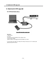
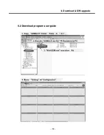
Page 114: ...6 Download S W upgrade 115 6 2 Download program user guide ...
Page 115: ... 116 6 Download S W upgrade ...
Page 116: ... 117 6 Download S W upgrade ...
Page 117: ... 118 6 Download S W upgrade ...
Page 124: ... 125 8 PCB LAYOUT ...
Page 125: ... 126 8 PCB LAYOUT ...
Page 126: ... 127 8 PCB LAYOUT ...
Page 127: ... 128 8 PCB LAYOUT ...
Page 141: ... 142 ...
Page 161: ...Note ...
Page 162: ...Note ...


