Making adjustments to the image size, position and
operating parameters of the monitor are quick and easy
with the On Screen Display Control system. A quick
example is given below to familiarize you with the use of
the controls. Following section is an outline of the
available adjustments and selections you can make using
the OSD.
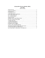
To make adjustments in the On Screen Display, follow
these steps:
1. Press the MENU Button, the main menu of the OSD
will appear.
2. To access a control, use the DOWN/UP ( )
Buttons. When the desired control icon is highlighted,
press the SET Button.
3. Press the DOWN/UP ( ) Buttons to select the
desired item.
4. Use the VOLUME ( ) Buttons to adjust the item
to the desired level.
5. Accept the changes by pressing the SET Button.
6. Exit the OSD by Pressing the MENU Button.
VOLUME
MENU
MENU
DOWN/UP
SET
SET
DOWN/UP
NOTE
Allow the monitor to stabilize for at least 30 minutes
before making image adjustment.
- 7 -
Listed below are the icons, icon names, and icon
descriptions of the items that are shown on the Menu.
Adjusting the Screen when Using a Computer
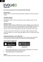
Brightness
Used to adjust the brightness of the screen.
Contrast
Adjust the display to the contrast desired.
USER
9300K
6500K
RED / GREEN / BLUE
To set your own color levels.
To appear the displays color temperature.
•
9300K:Slightly bluish white.
•
6500K:Slightly reddish white.
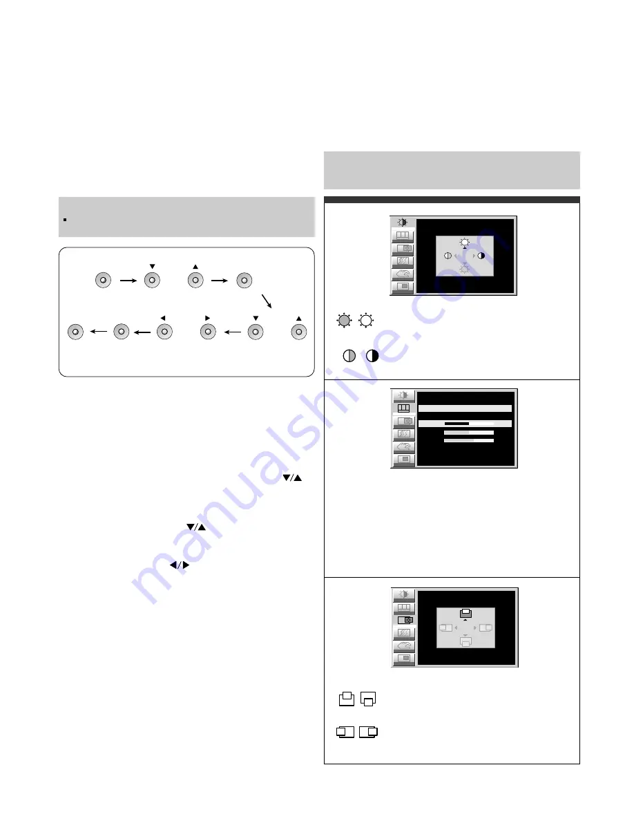
Vertical Position
To move image up and down.
Horizontal Position
To move picture image left and right.
Note : When a digital signal is set as an input, only the
SETUP item can be adjusted. You do not need to adjust
the other items.
Image
R G B
Color
Position
Setup
PIP
CONTRAST/BRIGHTNESS
CONTRAST
BRIGHTNESS
100
100
Tracking
Position
Setup
PIP
Tracking
Image
R G B
Color
COLOR ADJUSTMENT
USER
9300K
6500K
50
RED
50
GREEN
60
BLUE
R G B
Color
Setup
PIP
Tracking
IMAGE POSITION
VERTICAL
HORIZONTAL
50
50
Image
Position
Summary of Contents for FPD2200
Page 10: ... 10 WIRING DIAGRAM J21 J1 J11 J12 J2 J4 J19 CN1 CN3 CN2 CN4 CN5 P No 6631T11006B ...
Page 24: ...1 13 8 2 6 5 9 12 10 11 7 3 4 24 EXPLODED VIEW 14 15 16 17 18 ...
Page 34: ...SCHEMATIC DIAGRAM 34 1 ...
Page 35: ... 35 2 AD9884 ...
Page 36: ... 36 3 VIDEO PROCESSOR ...
Page 37: ... 37 4 MEMORY ...
Page 38: ... 38 5 A V INPUT ...
Page 39: ... 39 6 VIDEO PROCESS ...
Page 40: ... 40 7 TRANSMITTER SIL160 ...
Page 41: ... 41 8 POWER CONNECTOR INVERTER MODULE POWER ...
Page 42: ... 42 9 KEY PART ...