background image

TRAINING MANUAL 


DLEX8377WM  


DLEX8388WM 

Page 9 

STEAM DRYER 


ACCESSORIES 


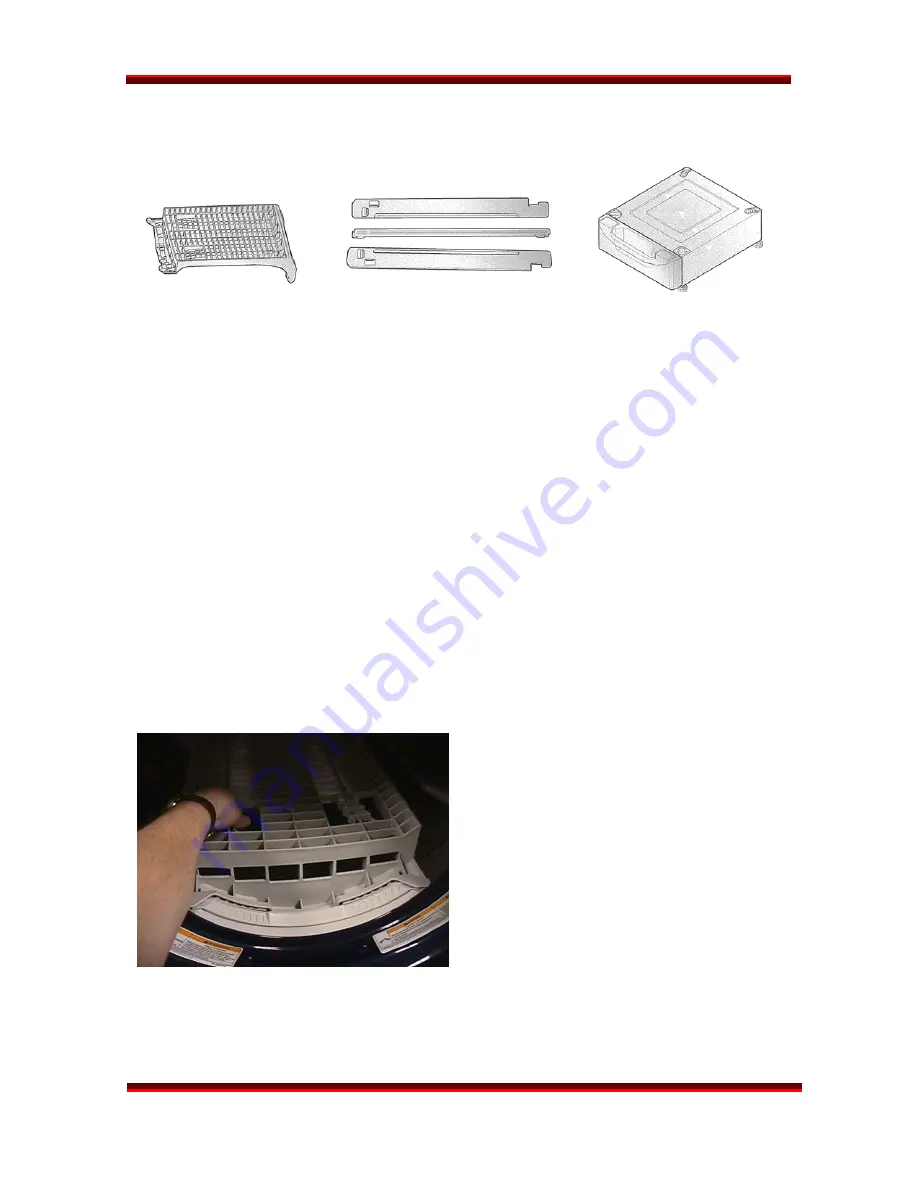
        DRYING RACK                  STACKING KIT 

             PEDESTAL 

 
The DRYING RACK is used to dry items that should not be tumbled, like sweaters, tennis 

shoes, etc. It should be removed and stored when not in use. The rack is included with 
the dryer. (See installation procedure, below.) 
 
The STACKING KIT is used to stack a dryer on top of a matching washer. (NEVER put a 
washer on top of a dryer!) The stacking kit should not be used in situation where there is 
the possibility of excessive vibration and movement of the washer, such as in a mobile 
home or an upper floor of a frame structure. The stacking kit is available as an optional 
purchase. (See installation procedure, page 10.) 
 

The PEDESTAL can be used under either the washer or the dryer. It is possible to stack a 

washer and dryer on a pedestal, but the dryer controls may be difficult to reach and the 

possibility of vibration and movement is greater. The pedestal is available as an optional 
purchase. (See installation procedure, pages 12 

~

 13.) Pedestals are available in heights 

of 7

¼

” and 13”.  


INSTALLATION 

(RACK) 


Open the dryer door.  
 
Put the rack in place. 

 
Select RACK DRY (2

nd

 button on right) 

 
Press START. 


Be sure the front of the rack is properly 
situated in the notches on either side  

of the filter. The back should rest on the 
drum and allow the drum to rotate. 


Summary of Contents for DLEX8377WM - SteamDryer Series - 27in Front-Load Electric Dryer

Page 1: ...LG TRAINING MANUAL LG TRAINING MANUAL Steam Dryers DLEX8377 M DLG8388 M Fall 2008 ...

Page 2: ...ademy com Technical training Contact Number Hours of Operation Customer Service 800 243 0000 24 7 365 days a year Technical Support 800 847 7597 7am 7pm Mon Fri Sat 8 2 CST Parts Sales 888 393 6484 7am 7pm Mon Sat CST Training Center 256 774 4051 8am 5pm Mon Fri CST Published August 2008 by LG Electronics USA Trainng Center Copyright 2008 LG Electronics of Alabama Inc Phone Contacts Web Contacts ...

Page 3: ...metal in the appliance Before removing a replacement part from its package touch the anti static bag to a ground connection point or unpainted metal in the appliance Handle the electronic control assembly by its edges only When repackaging a failed electronic control assembly in an anti static bag observe these same precautions REGULATORY INFORMATION This equipment has been tested and found to com...

Page 4: ...ycle Information 20 STEAMFRESH 20 Reduce Static 20 Easy Iron 20 Display PWB 21 Main Control Board 21 Main Control Board Photo with connectors labeled 22 Schematic Electric Dryer 23 Schematic Gas Dryer 24 Diagnostic Test Mode 25 Component Testing Procedures 26 Motor Diagram and Schematic 29 Safety Switches 30 Centrifugal Switch 30 Belt Switch 30 Diagnostic Test Procedures 31 Test 1 AC Electrical Su...

Page 5: ...Generator Troubleshooting 50 Main Components 50 Theory of Operation 50 Thermistor Testing 51 Pump Motor Testing 51 Panel Body and Frame 53 Tub Front Front Bulkhead 53 Drum Belt and Pulley 54 Drum Lamp 55 Vent Replacement Side Venting Kit 56 Additional Venting Information 57 Static Pressure Testing and Vent Kit 58 Filter Assembly and Moisture Sensor 59 Rear Bulkhead 59 Air Duct 59 Rollers 60 Blower...

Page 6: ... and an array of option buttons The steam feature buttons REDUCE STATIC and EASY IRON add these steam features to the end of any of the sensor cycles available See complete explanation on page 20 1 Cycle selected 2 Approximate time remaining on cycle 3 Progress indicator age complete 4 Child Lock indicator 5 Sensor cycle indicator 6 Indicators refer to the option buttons below the window These but...

Page 7: ... DLEX8388WM Page 5 STEAM DRYER INTRODUCTION continued MAIN PANEL New features on the control panel include the STEAM FUNCTION BUTTONS and the ADD WATER warning lamp The option buttons are the same on both types of control panel ...

Page 8: ...nnect gas piping re jet or adjust burners or repair gas fired equipment unless you are licensed and certified so to do It is the servicer s responsibility to comply with all such regulation The STEAM GENERATOR operates at a high temperature hot enough to boil water When servicing the steam generator let it cool before beginning work Hot water and steam can cause severe burns and injuries ...

Page 9: ...8388WM Page 7 STEAM DRYER WARRANTY Warranty statements vary by product Be sure to check the warranty that was included with the product because that is the valid warranty This statement is generic and for instructional purposes only ...

Page 10: ...TRAINING MANUAL DLEX8377WM DLEX8388WM Page 8 STEAM DRYER SPECIFICATIONS Specifications are subject to change without notice ...

Page 11: ... mobile home or an upper floor of a frame structure The stacking kit is available as an optional purchase See installation procedure page 10 The PEDESTAL can be used under either the washer or the dryer It is possible to stack a washer and dryer on a pedestal but the dryer controls may be difficult to reach and the possibility of vibration and movement is greater The pedestal is available as an op...

Page 12: ...lan to use a pedestal install it now before going any further Peel the protective paper from the adhesive tape on the side bracket Fit the side bracket firmly to the top plate using the adhesive tape as shown in the drawing Secure the bracket to the top plate using a screw as shown Repeat these steps for the other side Level the dryer on a firm solid floor and lock down the adjusters before placin...

Page 13: ...attach the front rail to the side bracket Insert the other screw for the other side INSTALLATION Makeup Air Minimum clearances must be observed particularly if the dryer is installed in a closet or a laundry alcove The dryer is essentially an air pump moving 150 cfm cubic feet per minute and that air must come from somewhere for the dryer to operate properly Additional air must be supplied to supp...

Page 14: ...down all four adjusters on the dryer Note which holes are for the washer and which are for the dryer If you are stacking the appliances the washer should be on the bottom Remove the protective paper from the adhesive surface of the bracket Be particularly careful because when this adhesive makes contact there is no adjustment possible NOTE Some kits include two sets of brackets curved for the drye...

Page 15: ...r one fourth turn with the adjusting wrench to put a little pressure between the dryer and pedestal to prevent any motion and rattling Push the dryer into place Check the level and adjust the front legs of the pedestal as necessary Then lock down the adjusters The pedestal kit includes the mounting plates with adhesive covered by paper and the screws to attach the plates Remember some pedestal kit...

Page 16: ...the modem cover Save the cover for future use in the event you must remove the modem you can replace the cover Attach the modem to the socket with the screws provided Plug the monitor s power cord in an outlet where you can observe it easily Use the stand or the wall mount bracket Press and hold the button until the display shows SET The dryer can be operated normally without the modem if the cust...

Page 17: ... mobile homes recreational vehicles and where prohibited by local code 4 wire Connection The 4 wire receptacle looks like this Power cord with spade terminals Power cord with ring terminals Install a strain relief on the power cord Then connect the terminals to the terminal block matching the wire colors A Ground screw on chassis B Green wire from power cord C Strain relief D Neutral screw on term...

Page 18: ... spade terminals Power cord with ring terminals Install a strain relief on the power cord Then connect the terminals to the terminal block matching the wire colors Add a wire to connect the chassis ground to neutral A Ground screw on chassis B Green wire from power cord C Strain relief D Neutral screw on terminal block E Ground to neutral connection F Neutral wire from power cord ...

Page 19: ...You want a secure connection without damage to the connectors Be sure to install a strain relief on the power cord Replace the terminal block cover by inserting the tabs into the slots and letting them slide down to engage Fold it over to the back of the dryer so it covers the access to the terminal block Be sure no wires are exposed or could touch any metal surface Secure the cover with a screw ...

Page 20: ... most locations installing and connecting gas is restricted to properly trained and licensed persons Always inspect joints and connections for a leak with a soapy solution If you see bubbles turn the gas off and open a window If you smell gas turn off the main valve and open a window The gas dryer requires a 120 VAC single outlet dedicated circuit The cord is installed at the factory and no user i...

Page 21: ...DRYER CYCLE CHART SENSOR DRY The dryness level is set by the customer MANUAL DRY The temperature is set by the customer The maximum drying time for RACK DRY or SPEED DRY is 1 hour 39 minutes The default settings can be overridden by the customer in most cases ...

Page 22: ... last two minutes of the cycle while the drum continues to tumble to allow the clothes to cool The MORE TIME and LESS TIME buttons are used to adjust the number of items to be freshened during the STEAMFRESH cycle The time cannot be adjusted by the user when a sensor dry cycle is engaged REDUCE STATIC The REDUCE STATIC cycle is an add on to all the regular cycles except AIR DRY or RACK DRY When RE...

Page 23: ...EDs that indicate the various cycle and option information It is made of two boards that are permanently connected by a ribbon cable that is soldered to the board at each end This makes the boards a single unit The purpose is to allow the display board to flex to fit inside a curved control panel while maintaining its integrity as a single board MAIN CONTROL BOARD The main board is attached to the...

Page 24: ...TRAINING MANUAL DLEX8377WM DLEX8388WM Page 22 STEAM DRYER MAIN PWB The main board includes the relays that operate electric heaters and gas valves The gas and electric models have a different main board ...

Page 25: ...TRAINING MANUAL DLEX8377WM DLEX8388WM Page 23 STEAM DRYER SCHEMATIC ELECTRIC DRYER ...

Page 26: ...TRAINING MANUAL DLEX8377WM DLEX8388WM Page 24 STEAM DRYER SCHEMATIC GAS DRYER ...

Page 27: ...e thermostat attached to the heater 1 Dryer must be in standby mode Plugged in turned off 2 Press and hold MORE TIME and LESS TIME then press power 3 Press START PAUSE to advance to the next test 4 Unplug the dryer for one minute after using the diagnostic mode NOTE During Test 4 The Steam Generator pump will flood the dryer if allowed to run very long This is normal so do not stay on this test ve...

Page 28: ...TEAM DRYER COMPONENT TESTING PROCEDURES Testing the various components of the dryer is relatively simple Most can be checked without major disassembly of the dryer Many can be checked by removing that component s connector at the main control board ...

Page 29: ...TRAINING MANUAL DLEX8377WM DLEX8388WM Page 27 STEAM DRYER COMPONENT TESTING PROCEDURES continued ...

Page 30: ...TRAINING MANUAL DLEX8377WM DLEX8388WM Page 28 STEAM DRYER COMPONENT TESTING PROCEDURES continued ...

Page 31: ... STEAM DRYER MOTOR DIAGRAM and SCHEMATIC To check the motor turn the power off and allow the capacitor to discharge The centrifugal switch serves as a safety device to turn off the fuel gas or electricity to the heater if the motor fails to rotate ...

Page 32: ... element or gas valve If the motor stops the weight slides forward and turns the power off RUN POSITION STOP POSITION There is an additional safety in the form of a belt switch that shuts off power to the electric motor if the belt breaks Belt tension holds the switch closed If the belt breaks the switch opens and power to the motor is cut When the motor stops the centrifugal switch functions as a...

Page 33: ...ng issues with the dryer Each test will list the appropriate precautionary measures along with symptoms and the conditions under which the testing should be performed TEST 1 AC ELECTRICAL SUPPLY WARNING Use insulated gloves to avoid electrical shock SYMPTOM No power display off CONDITION Power on to dryer controller connected continued on next page ...

Page 34: ... MANUAL DLEX8377WM DLEX8388WM Page 32 STEAM DRYER WARNING Use insulated gloves to avoid electrical shock SYMPTOM Check the TAB RELAY connections CONDITION Power on to dryer controller connected POWER CONNECTION ...

Page 35: ... STEAM DRYER CONNECTION STATUS Electric CONNECTION STATUS Electric If the power connection is reversed the dryer will not operate and components can be damaged CONNECTION STATUS REVERSED Incorrect Electric CONNECTION STATUS REVERSED Incorrect Gas ...

Page 36: ...DRYER TEST 2 Thermistor Test Power Off WARNING Use insulated gloves to avoid electrical shock SYMPTOM tE1 and tE2 error codes occur during the test Heater does not turn off Significant difference between actual and sensed temperature CONDITION Power off ...

Page 37: ...TEAM DRYER TEST 3 Motor Test WARNING Discharge see below before measuring resistance SYMPTOM Motor fan and heater do not function CONDITION Turn power off unplug dryer and discharge by shorting line and neutral to ground at the end of the power cord ...

Page 38: ...sture Sensor Test WARNING Discharge see below before measuring resistance SYMPTOM Dryness of clothing does not match set dry level CONDITION Turn power off unplug dryer and discharge by shorting line and neutral to ground at the end of the power cord Measure resistance ...

Page 39: ...WM DLEX8388WM Page 37 STEAM DRYER TEST 5 Door Switch Test WARNING Discharge before measuring resistance SYMPTOM Door opening not sensed dryer runs with door open CONDITION Turn dryer off unplug discharge and measure resistance ...

Page 40: ...8377WM DLEX8388WM Page 38 STEAM DRYER TEST 6 Heater Switch Electric Dryer Only WARNING Discharge before measuring resistance SYMPTOM Heater does not operate CONDITION Turn power off unplug discharge and measure resistance ...

Page 41: ...TRAINING MANUAL DLEX8377WM DLEX8388WM Page 39 STEAM DRYER TEST 7 Gas Valve Test Gas Dryer Only WARNING Use insulated gloves to avoid electrical shock SYMPTOM Heater does not operate CONDITION Power on ...

Page 42: ...LEX8377WM DLEX8388WM Page 40 STEAM DRYER TEST 8 Semiconductor Sensor Test WARNING Discharge before measuring resistance SYMPTOM Resistance is not 300Ω 20Ω CONDITION Turn power off unplug discharge and measure resistance ...

Page 43: ...CE The dryer is shipped from the factory equipped for natural gas 1 Close the adjustment screw There is a nut on the adjustment screw This nut is secured to the thread with a sealing compound The nut is pre positioned to the place the valve would be properly adjusted for LP Its purpose is to provide a shoulder for positioning the adjustment screw if the dryer is converted from natural gas to propa...

Page 44: ...tructions for making the conversion and a label indicating the conversion kit has been installed All conversion work including testing and adjusting must be completed by a trained licensed and certified gasfitter 4 Be sure to retain the original orifice in the event that the dryer should be converted back to natural gas Put it into the plastic bag for the original orifice and tape it to the inside...

Page 45: ...hould check the pressure on the incoming gas line To test the gas pressure burner operation gas dryer or heater electric dryer the servicer must fabricate a bulkhead cover to allow the blower to pull through the system as if the dryer were fully assembled and in normal operation To accomplish this remove the front cover tape the door switch into the closed position and cover the door opening with ...

Page 46: ...e igniter is turned on and valve one opens When the igniter reaches 374 F 190 C the igniter is turned off and valve two is opened If the flame detector does not detect ignition valve one is closed and the process is restarted If ignition occurs as planned the drying cycle will operate GAS IGNITION SEQUENCE GAS VALVE CONSTRUCTION IGNITION FLOW CHART ...

Page 47: ...ard and take the guard off Remove three screws attaching the top plate Slide the top plate backward Lift the top plate off and set it aside PANEL DRAWER Open the drawer Remove the water tank Pull the drawer to full extension lift the retaining tab and take the drawer out of the dryer Remove the two screws at the sides of the drawer opening ...

Page 48: ... The connectors are all different in pin count configuration and color coding to prevent misassembly Pull the control panel upward then forward Be sure to disengage all the plastic tabs along the top Lay the control panel on its face on a soft protective cloth Remove 2 screws on the main PWB Remove 6 screws on the display PWB Disassemble the control panel ...

Page 49: ...ttom of the door opening Remove four screws from the top of the front cabinet Tilt the front away from the dryer and disconnect the door switch wire harness DOOR REVERSAL Remove two screws that hold the door Remove the door and set it aside on a soft protective cloth Save the hinge shim Remove two screws near the latch Remove two screws and the latch piece Rotate everything 180 and reinstall so th...

Page 50: ...onnect the hose from the steam orifice on the back of the dryer Use water pump pliers to remove the hose clamps Push the water system guide assembly toward the back of the dryer and lift it from the dryer Remove the hoses from the pump and the steam generator Use water pump pliers to remove the hose clamps Lift the pump and the steam generator out of the assembly housing ...

Page 51: ... load the steam heater and pump will not be energized The steam is created by boiling water in the steam generator and piping the steam into the back of the dryer drum through a nozzle toward the top of the back The water drawer pump and steam generator are mounted in the guide assembly on the left side of the dryer The tank is accessible by pulling out the drawer on the control panel Use ordinary...

Page 52: ...ntrol board determine IF the steam generator heater will be activated See the wiring diagram for the water level sensors and steam generator heater The picture above shows 3 connectors The left most connector with black and gray leads is the temperature sensing thermistor The center connector with a black and orange wire is the low water sensor The front connector with a single brown wire is the h...

Page 53: ...rol board would activate the 9 VDC water pump for the steam generator before energizing the heater IF steam was selected and the control board wanted steam We see the meter displaying 1 5 VDC In this example the water in the housing is touching the high water sensor probe and the ground probe When this occurs conductivity through the water is measured as a voltage drop and the control board knows ...

Page 54: ... is approximately 3 3KΏ and the voltage measure across the sensor is 88 VDC The dryer is not connected to cold water plumbing but relies on a water reservoir and a pump motor The water pump is powered by the control board from CON RD6 yellow 9 VDC to blue Ground To test the motor 1 place your meter leads across the motor connector 2 remove the single connector from the high water sensor BN wire 3 ...

Page 55: ...anel frame Remove the two screws from the top of the front panel frame Remove the panel frame from the front of the dryer by lifting it slightly and disengaging the tab on each end from the slot in the dryer frame TUB FRONT FRONT BULKHEAD Remove the top plate Remove the front cabinet Disconnect the door lamp top and electrode sensor bottom Remove the four screws holding the front assembly Lift the...

Page 56: ...drum put the belt around it and set into the dryer to rest on the two rubber wheels on the tub back Let the belt hang Replace the tub front holding the drum up so it can set on the two rubber wheels on the tub front Make sure the belt is around the circumference of the drum near the point where it usually rides Reach in through the front or the side and loop the belt around the motor shaft and the...

Page 57: ...get to the socket Open the door Hold the lamp shield in place and remove the screw Slide the shield toward the screw and remove it Unscrew the bulb and replace it with a 15 watt 120 V candelabra base bulb Replace the shield and screw Notice the bulb holder has feet that hold it in place and tabs to keep it positioned properly The socket can be removed and replaced by squeezing the tabs and pulling...

Page 58: ...eft right or bottom as necessary Right vent option not available on gas dryers due to internal piping interference B Insert the replacement pipe C Attach the pipe with a screw Pre assemble the elbow and a replacement duct and secure the joint with duct tape Insert the pre assembled elbow into the dryer through the vent hole and connect it to the internal pipe Tear off some pieces of duct tape and ...

Page 59: ...ressure in the vent Static pressure should be no greater than 0 6 inches of water column REMINDER If you have installed the side vent kit remember the kit includes a 90 elbow inside the dryer which counts as one elbow in the vent system and this must be taken into account when figuring vent length and static pressure measurements It is sometimes necessary to use a section of test pipe with a fitti...

Page 60: ...ecessary to convert the dryer vent to a side or rear connection One of the straight pipes includes a tab welded to it to keep it from vibrating loose inside the dryer The cover plate includes a screw for attachment at the original vent exit so vermin do not crawl into the machine Full instructions are included and it is not necessary to disassemble the dryer to install the vent kit ...

Page 61: ...rs REAR BULKHEAD Remove the top plate front cover and tub front Remove the belt and lift out the drum Remove 7 screws from the outside of the rear cover being careful the rear bulkhead does not fall and cause internal damage Remove the rear bulkhead from inside the dryer cabinet AIR DUCT Remove the top plate Remove the front cover Remove the filter Remove 2 screws at the top of the air duct Remove...

Page 62: ...If the shaft is undamaged you can replace only the roller Squeeze the triangular retainer to remove and replace the roller without removing the shaft from the machine Be sure to install the small bushings These must be between the roller and the retainer on both sides of the roller See photo Some models are supplied with an updated roller assembly that does not include the bushings These assemblie...

Page 63: ...nt cover Remove the tub front Remove the drum Remove the two screws and the cover on the air guide Remove the nut and washer on the blower shaft CAUTION The blower nut is a left handed thread Remove the fan from the shaft Press down the hooked end of the clamps and remove them Disconnect and remove the motor ...

Page 64: ...TRAINING MANUAL DLEX8377WM DLEX8388WM Page 62 STEAM DRYER EXPLODED VIEW Control Panel and Top Plate Assembly ...

Page 65: ...TRAINING MANUAL DLEX8377WM DLEX8388WM Page 63 STEAM DRYER EXPLODED VIEW Panel Drawer Assembly and Guide Assembly ...

Page 66: ...TRAINING MANUAL DLEX8377WM DLEX8388WM Page 64 STEAM DRYER EXPLODED VIEW Cabinet and Door Assembly ...

Page 67: ...TRAINING MANUAL DLEX8377WM DLEX8388WM Page 65 STEAM DRYER EXPLODED VIEW Drum and Motor Electric Model ...

Page 68: ...TRAINING MANUAL DLEX8377WM DLEX8388WM Page 66 STEAM DRYER EXPLODED VIEW Burner and Related Parts Gas Model ...

Page 69: ...K38392501 Cover Guide A210 3457ER1006X Plate Assembly Top A211 3300EL2001E Plate Upper A300 4810EL3006A Bracket Hinge A305 4810EL3006B Bracket Hinge A310 3551EL0009K Cover Assembly Cabinet A320 4027EL1001A Locker Assembly A330 6601EL3001A Switch Assembly Door Safety A390 ADV33609802 Frame Assembly A400 3581EL0004A Door Assembly A410 4026EL3007A Locker Hook A420 3212EL1015A Frame Door Outer A430 47...

Page 70: ...mp Incandescent Entire Assembly K222 6913EL3001A Lamp Incandescent Bulb Only K230 3550EL2001A Cover Lamp K240 5209EL1002A Duct Assembly K250 4581EL2002A Roller Assembly Wheel Shaft and Parts K251 4581EL3001A Roller Assembly Wheel Only K310 5231EL1003B Filter Assembly Lint K320 3550EL1006B Cover Guide K330 4974EL1003B Guide Filter K340 6500EL3001A Sensor Bars K350 6631EL3003B Single Harness K360 49...

Page 71: ...witch K650 4561EL3002A Pulley Assembly Motor with Wheel K651 4560EL3001A Pulley Idle Wheel Only M110 5221EL2002A Valve Assembly Gas M140 4974EL1001A Guide Burner M141 4810EL3002A Bracket Base M150 5201EL3001A Pipe Assembly M160 5318EL3001A Igniter M170 4948EL4001B Orifice Natural Gas M171 4948EL4002B Orifice Propane M180 4932EL4001A Connector Mechanical Pipe M181 4036EL3002A Seal M190 5201EL2001A ...

Page 72: ... change was made Some models may have four 4 letters instead of two 2 for the product code number The third and fourth letters are significant only to the manufacturing facility This chart will help you decode the serial number Example 801KW3400251 801 KW 00251 Production Number Internal code Manufactured January 2008 34 Made in Korea Newer Style With Barcode Sequential number Internal code Model ...

Page 73: ...s Watts Amperes2 x Ohms Watts Volts x Amperes I AMPERES Amperes Volts Ohms Amperes Watts Volts Amperes I R 2 E R 2 P R P I E I E R P E P R P I 2 E P 2 P E I I R I E R WATTS CURRENT VOLTS OHMS E VOLTS Volts Volts Watts Amperes Volts Amperes x Ohms R OHMS Ohms Volts Amperes Ohms Volts2 Watts Ohms Watts Amperes2 ...

Page 74: ...TRAINING MANUAL DLEX8377WM DLEX8388WM Page 72 STEAM DRYER CONVERSION INFORMATION FORMULAE F 9 5 C 32 C 5 9 x F 32 ...

Page 75: ...TRAINING MANUAL DLEX8377WM DLEX8388WM Page 73 STEAM DRYER SERVICE BULLETINS ...

Page 76: ...TRAINING MANUAL DLEX8377WM DLEX8388WM Page 74 STEAM DRYER ...

Page 77: ...TRAINING MANUAL DLEX8377WM DLEX8388WM Page 75 STEAM DRYER ...

Page 78: ...TRAINING MANUAL DLEX8377WM DLEX8388WM Page 76 STEAM DRYER ...

Page 79: ...TRAINING MANUAL DLEX8377WM DLEX8388WM Page 77 STEAM DRYER ...

Page 80: ...TRAINING MANUAL DLEX8377WM DLEX8388WM Page 78 STEAM DRYER ...

Page 81: ...TRAINING MANUAL DLEX8377WM DLEX8388WM Page 79 STEAM DRYER ...

Page 82: ...TRAINING MANUAL DLEX8377WM DLEX8388WM Page 80 STEAM DRYER ...

Page 83: ...TRAINING MANUAL DLEX8377WM DLEX8388WM Page 81 STEAM DRYER ...

Page 84: ...TRAINING MANUAL DLEX8377WM DLEX8388WM Page 82 STEAM DRYER ...

Page 85: ......

Page 86: ...Steam Dryer Fall 2008 ...

Reviews: