background image

10

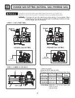
CHANGE GAS SETTING (NATURAL GAS, PROPANE GAS)

28

Natural Gas mode is  set.  Propane Gas Orifice is on sale as a Service
Part to authorized servicers only.

STEP 1 : VALVE SETTING

STEP 2 : ORIFICE CHANGE 

Natural Gas

Propane Gas

4948EL4001B

4948EL4002C

Kit contents:

Orifice (Dia. = 1.47mm, for Propane Gas)

Conversion Label

Instruction Sheet

NCU

PCK

Remove 2 screws.

Disassemble the pipe assembly.

Replace Natural Gas orifice with Propane Gas orifice.

Opened

Closed

Orifice

Initially,

Changing orifices and gas valve adjustments improperly can result in an
explosion and/or fire. Conversion must be made by a qualified technician.

!

Warning 

The burner is set for natural gas at the factory. The propane orifice

conversion kit is sold as a service part to autherized servicers only.

Part numbers are shown below.

Full open

Adjustment screw

Close

Adjustment screw

Summary of Contents for DLE1501W

Page 1: ...RVICE MANUAL CAUTION READ THIS MANUAL CAREFULLY IN ORDER TO PROPERLY DIAGNOSE PROBLEMS AND TO SAFELY PROVIDE QUALITY SERVICE ON THESE DRYERS U S A Website http us lgservice com Canadian Website http lg ca DLE1501W DLG1501W ...

Page 2: ...for service they must be returned to their original position and properly fastened IMPORTANT ESD problems are present everywhere ESD may damage or weaken the electronic control assembly The new control assembly may appear to work well after repair is finished but failure may occur at a later date due to ESD stress એ Use an anti static wrist strap Connect wrist strap to green ground connection poin...

Page 3: ...STOR TEST MEASURE WITH POWER OFF 22 9 3 TEST 3 MOTOR TEST 23 9 4 TEST 4 MOISTURE SENSOR 24 9 5 TEST 5 DOOR SWITCH TEST 25 9 6 TEST 6 HEATER SWITCH TEST ELECTRIC TYPE 26 9 7 TEST 7 GAS VALVE TEST GAS TYPE 27 10 CHANGE GAS SETTING NATURAL GAS PROPANE GAS 28 11 DISASSEMBLY INSTRUCTIONS 30 12 EXPLODED VIEW 37 12 1 1 CONTROL PANEL AND PLATE ASSEMBLY ELECTRIC TYPE 37 12 1 2 CONTROL PANEL AND PLATE ASSEM...

Page 4: ... dryer Gas 120 VAC Electric 240VAC Specifications are subject to change by manufacturer Size 27 X 403 16 X 29 inch Dryer capacity IEC 7 3 cu ft Weight Gas 136 4 Ibs 61 89kg Electric 133 7lbs 60 63kg See page 6 of this manual for usage instruction Dryer rack 1 each ACCESSORY Optional accessory ...

Page 5: ...e Door Drum Child Lock Interior Light Product WxHxD Packing WxHxD Sensor POWER SUPPLY Material Finish Silver 120 240V60Hz 26A 120 208V60Hz 23A 120V 60Hz 11 5A 250W 4 5A 5400W 22 5A 4100W 21A 15 W 0 2A 13 W 0 11A x 2 Electronic 7 3 cu ft Gas136 4Ibs 61 89kg Electric133 7lbs 60 63kg 12 7 5 5 Available Available Available Alcosta Available Available 27 x 403 16 x 29 inch 29 x 403 x 30 inch AC 120V AC...

Page 6: ...ITS 6 3 INSTALLATION INSTRUCTIONS Open the door Hold the dryer rack with both hands Put the dryer rack into the drum Check and be sure that the front of the rack is properly seated behind the lint filter Optional accessory ...

Page 7: ...s permit the connection of a chassis ground to the neutral connector If this is not permitted use option 3 4 wire receptacle Review the following options to determine the appropriate electrical connection for your home NEMA type14 30R NEMA type10 30R 3 wire receptacle Option 2 3 Wire Connection with a Power Supply Cord 3 Connect the ground wire green of the power cord to the external ground screw ...
Page 8: ...using a new flexible stainless steel connector 4 Tighten all connections securely Turn on gas and check all pipe connections internal external for gas leaks with a non corrosive leak detection fluid 5 For LP Liquefied Petroleum gas connection refer to section on Gas Requirements 1 New Stainless Steel Flexible Connector Use only if allowed by local codes Use Design A G A Certified Connector 2 NPT P...

Page 9: ...9 Connect Inlet Hose Only for Steam model RQNX QUP XPP XPP ...

Page 10: ...4 DRYER CYCLE PROCESS 10 Sensor dry Dry Level is set by users Manual dry Temperature control is set by users Default settings can be adjusted by users 28min ...

Page 11: ...11 5 COMPONENT TESTING INFORMATION ...

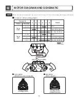
Page 12: ...erminal Valve 1 terminal Valve 2 terminal 8 Thermistor Measure resistance of terminal to terminal Temperature condition 9 Motor 10 Gas valve Resistance value 20 Resistance value 20 Resistance value 40 Resistance value 10 valve 1 valve 2 Component Test Procedure Check result Remark Resistance value 1 5 2 5 13 Resistance value 100 800 12 Frame Detect Measure resistance of termina to terminal Resista...

Page 13: ...s type Electric type Gas funnel Measure resistance of terminal to terminal Open at 212 12 F 110 7 C Manual reset If thermal fuse is open must be replaced Resistance value Continuity 1Ω Check Top Marking N95 Check Top Marking N110 Resistance value Continuity 1Ω Component Test Procedure Check result Remark 15 Inlet valve Measure resistance of the Following terminal Left picture plate ...

Page 14: ... Contact On Off by Centrifugal Switch RUN MODE Motor operates STOP MODE When Motor does not operate Motor 2 3Ω 3 5Ω 1Ω 1Ω Terminal No Mode Centrifugal switch Centrifugal switch Pull Drive forward Resistance Remark Motor STOP Motor RUN Motor Heater Electric Models Heater Electric Models Gas Valve Gas Models Gas Valve Gas Models ...

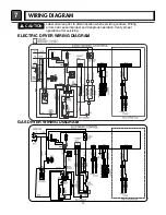
Page 15: ...7 WIRING DIAGRAM 15 ...

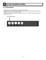
Page 16: ...d duct vents or hoses decrease e fficiency in drying clothes Clogged vents can also cause fire This function alarms you when to clean the ducts When the alarm about duct clogging is on display of the panel your duct vents should be cleaned by yourself or serviceman 8 1 Flow sensor Flow Sensor Function ...

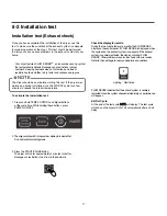
Page 17: ... testing mode 3 Press the START PAUSE button The dryer will run for approximately 2 minutes to test for blockages or restrictions to air flow in the ductwork Check the display for results During the two minute test cycle monitor the FLOW SENSE display on the control panel If FLOW SENSE is displayed when the cycle ends the exhaust system is adequate If the exhaust system is severely restricted the ...

Page 18: ...e exhaust system for restrictions and damage Repair or replace the exhaust system as needed NOTE When the dryer is first insralled this test should be performed to alert you to any existing problems with the exhaust duct in your home However since the test performed during normal operation provides more accurate information on the condition of the exhaust duct than does the installation test FLOW ...

Page 19: ...tricted Check for blockages and lint build up Avoid long runs of ducts or runs with multiple elbows or bends Control Panel 1 FLOW SENSE indicator light is on even when vents have been clean and even when the vents are off This is Normal After flow sensor recheck full next cycle flow sensor is reset Flow sensor bars will disappear after dryer has operated two cycle Bars Are Displayed but Don t Disa...

Page 20: ...r is contacted with damp cloth The display number is below180 in normal condition 235 Low moisture 30 High moisture Current Temp 5 70 Current Temp 5 70 Electric control Temperature sensor ELECTRIC TYPE Motor Heater1 2700 W GAS TYPE Motor ELECTRIC TYPE Motor Heater1 Heater2 5400W GAS TYPE Motor Gas valve Once Motor Controller Steam off Loads off Controller off Twice 3 times 5 times Motor Heater off...

Page 21: ...oltage 110V 125VAC YES NO Checkthefuse orcircuitbreaker Checkifthevoltagemeasuredbetween ConnectorBK2orWH2 BlackWire LinkedtotheControllerandBL2 WhiteWire Is110 125V YES NO 1 3 2 1 2 BK2 or WH2 BL2 WH BK CheckifPower Cordisproperly connected Reconnectthe controller ReplacecontroIler Checkif theControllerwireis disconnected CheckifTerminalBlockandPowerCord areconnected CheckPlug DoesPowerCordNneutr...

Page 22: ...22 Test 2 Thermistor Test Measure with Power Off NO NO YES YES Air TEMP 0 0 AirTEMP 1 2 2 32 31 RES K 3 0 1 2 RES K 0 0 3 2 RES 1 2 AirTEMP 2 3 3 45 0 Caution Trouble Symptom MeasurementCondition ഫ ...

Page 23: ...23 Test 3 Motor test Caution Trouble Symptom MeasurementCondition BL2 WH4 WH4 9 YES NO YES 9 0 1 YES NO 9 0 1 0 NO YES 9 2 YES NO 2 3 9 0 NO YES 3 4 1 3 3 3 2 1 3 4 2 1 3 4 2 ...

Page 24: ...Test 4 Moisture sensor 9 0 0 0 IMC 123 4 523 523 4 023 23 4 Display Value 62 4 72 72 4 02 026 4 052 Voltage DC between NA6 terminal 0 68 0 28 4 5 28 5 28 Remark Caution Trouble Symptom MeasurementCondition ...

Page 25: ...25 Test 5 Door switch test 1 1 2 BK2 BL2 9 9 09 1 09 1 YES YES YES YES NO NO NO NO Caution Trouble Symptom MeasurementCondition ...

Page 26: ...26 Test 6 Heater switch test Electric Type Caution Trouble Symptom Measurement Condition 9 YES NO 9 9 9 YES NO 9 0 YES NO 0 1 9 1 YES NO 0 1 1 0 1 1 1 1 0 1 1 2 3 41 1 0 2 3 ...

Page 27: ... than DC 90V 10 sec after Igniter off When measuring terminal resistance on valve 1 and valve 2 valves are more than1 5 2 5kΩ Measure after off If valve 1 and valve 2 are under DC 10V valves are Off Harness check Controller change Check thermostat hi limit safety Check Igniter frame detect Check gas connection or gas supply Change valve Change valve YES YES YES YES YES NO NO NO NO NO NO Valve 1 NO...

Page 28: ...on Sheet NCU PCK Remove 2 screws Disassemble the pipe assembly Replace Natural Gas orifice with Propane Gas orifice Opened Closed Orifice Initially Changing orifices and gas valve adjustments improperly can result in an explosion and or fire Conversion must be made by a qualified technician Warning The burner is set for natural gas at the factory The propane orifice conversion kit is sold as a ser...

Page 29: ...29 VALVE 1 IGNITER VALVE 2 FLAME DETECT NO NO YES YES ...

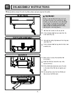
Page 30: ... use of long sleeved gloves and safety glasses 1 Remove the 2 screws that hold the PCB box in place 2 Slide the PCB box toward the rear of the dryer and lift out 3 With a flat blade screwdriver press the tabs on the side of the PCB box and gently pry it open 4 Disconnect the wiring from the PCB board then remove the PCB board DISASSEMBLY INSTRUCTIONS 1 Remove the 2 screws on the rear panel 2 Lift ...

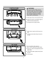
Page 31: ...panel assembly WARNING When you disassemble the Dryer be sure to disconnect the dryer from its electrical supply Protect your hands and arms from sharp edges when working To reduce the risk of personal injury adhere to all industry recommended safety procedures including the use of long sleeved gloves and safety glasses The inner top plate is held in place by 2 screws 1 on each side and the 2 plas...

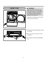
Page 32: ...r switch and lift the cabinet cover 4 Disconnect wiring to the door switch and lift the cabinet cover WARNING When you disassemble the Dryer be sure to disconnect the dryer from its electrical supply Protect your hands and arms from sharp edges when working To reduce the risk of personal injury adhere to all industry recommended safety procedures including the use of long sleeved gloves and safety...

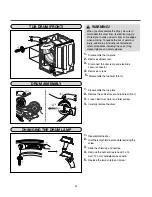
Page 33: ...s and safety glasses 1 Disassemble the top plate 2 Remove the cabinet cover and tub drum front 1 Disassemble the door 2 Hold the lamp shield in place while removing the screw 3 Slide the shield up and remove 4 Remove the bulb and replace with a 15 watt 120 volt candelabra base bulb 5 Replace the lamp shield and screw 1 Disassemble the top plate 2 Remove cabinet cover 4 Remove 4 screws 5 Disassembl...
Page 34: ...res including the use of long sleeved gloves and safety glasses 1 Remove screw and exhaust duct 2 Detach and remove the bottom left or right side knockout as desired Attach cover plate to the back of the dryer with included screw 4 Pre assemble a 4 elbow with a 4 duct Wrap duct tape around the joint 5 Insert duct assembly elbow first through the side opening and connect the elbow to the dryer Øs i...

Page 35: ...g sleeved gloves and safety glasses 1 Disassemble the top plate 2 Remove the cabinet cover and tub drum Front 1 Disassemble the top plate 2 Remove the cabinet cover and tub drum Front 3 Remove the drum assembly 4 Remove 7 screws 5 Pull the tub drum Rear towards the front 1 Remove the filter 2 Remove 3 screws 4 Disconnect the electrode sensor 5 Remove the bolt and washer 3 Remove the cover grid 3 R...

Page 36: ...try recommended safety procedures including the use of long sleeved gloves and safety glasses 1 Disassemble the top plate 2 Remove the cabinet cover and tub drum Front 1 Disassemble the top plate 2 Remove the cabinet cover 4 Remove the air duct 5 Remove the roller from the tub drum Front and tub drum Rear 3 Remove the filter and 2 screws 3 Remove the drum assembly and tub drum Rear 4 Disconnect th...

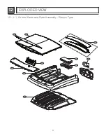
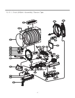
Page 37: ...37 12 EXPLODED VIEW 12 1 1 Control Panel and Plate Assembly Electric Type A150 A130 A213 A120 A215 A570 A118 A210 A115 A110 A116 ...

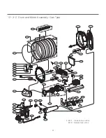
Page 38: ...38 12 1 2 Control Panel and Plate Assembly Gas Type A120 A150 A130 A213 A215 A210 A115 A110 A118 ...

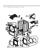
Page 39: ...39 12 2 1 Cabinet Door Assembly Electric Type A600 A800 A325 A320 A545 A500 A520 A540 A510 A310 A440 A450 A420 A430 A410 A475 A400 A330 A313 A131 A430 A314 A315 A470 A415 A580 A585 A700 ...

Page 40: ...40 12 2 2 Cabinet Door Assembly Gas Type A550 A800 A700 A320 A545 A500 A520 A540 A510 A310 A440 A450 A420 A430 A410 A475 A400 A330 A313 A314 A131 A430 A325 A470 A415 A580 A585 ...

Page 41: ...ctric Type K640 K660 K655 K120 K140 K310 K620 K610 K330 K340 K130 K100 K221 K222 K210 K240 K350 F130 F110 F120 F140 K510 K540 K650 K520 K550 K250 K560 K320 K251 K224 K230 K225 K400 F200 K250 K251 K360 K530 K651 K600 K515 K335 K336 F150 ...

Page 42: ...K510 M220 M240 M150 M141 M160 M171 M170 M140 M110 M181 M180 M190 M230 M250 K540 K650 K520 K550 K250 K560 K320 K251 K224 K230 K225 K250 K400 F200 K251 K360 K530 K651 K600 M210 M171 Propane Gas orifice M170 Natural Gas orifice K515 K660 K335 K336 12 3 2 Drum and Motor Assembly Gas Type ...

Page 43: ...May 2015 PRINTED IN KOREA P No MFL62119996 ...

Reviews: