background image

- 3 -

Copyright  © 

  LG Electronics. Inc. All rights reserved.

Only for training and service purposes

Many electrical and mechanical parts in this chassis have special safety-related characteristics. These parts are identified by      in the 
Schematic Diagram and Exploded View.
It is essential that these special safety parts should be replaced with the same components as recommended in this manual to prevent 
Shock, Fire, or other Hazards. 
Do not modify the original design without permission of manufacturer.

General Guidance

An 

isolation Transformer should always be used

 during the 

servicing of a receiver whose chassis is not isolated from the AC 
power line. Use a transformer of adequate power rating as this 
protects the technician from accidents resulting in personal injury 
from electrical shocks.

It will also protect the receiver and it's components from being 
damaged by accidental shorts of the circuitry that may be 
inadvertently introduced during the service operation.

If any fuse (or Fusible Resistor) in this TV receiver is blown, 
replace it with the specified.

When replacing a high wattage resistor (Oxide Metal Film Resistor, 
over 1 W), keep the resistor 10 mm away from PCB.

Keep wires away from high voltage or high temperature parts.

Before returning the receiver to the customer,


always perform an 

AC leakage current check

 on the exposed 

metallic parts of the cabinet, such as antennas, terminals, etc., to 
be sure the set is safe to operate without damage of electrical 
shock. 

Leakage Current Cold Check(Antenna Cold Check)

With the instrument AC plug removed from AC source, connect an 
electrical jumper across the two AC plug prongs. Place the AC 
switch in the on position, connect one lead of ohm-meter to the AC 
plug prongs tied together and touch other ohm-meter lead in turn to 
each exposed metallic parts such as antenna terminals, phone 
jacks, etc. 
If the exposed metallic part has a return path to the chassis, the 
measured resistance should be between 1 M

ȍ

 and 5.2 M

ȍ

When the exposed metal has no return path to the chassis the 
reading must be infinite.
An other abnormality exists that must be corrected before the 
receiver is returned to the customer.

Leakage Current Hot Check


(See below Figure) 

Plug the AC cord directly into the AC outlet.

Do not use a line Isolation Transformer during this check.


Connect 1.5 K / 10 watt resistor in parallel with a 0.15 uF capacitor 
between a known good earth ground (Water Pipe, Conduit, etc.) 
and the exposed metallic parts.
Measure the AC voltage across the resistor using AC voltmeter 
with 1000 ohms/volt or more sensitivity.
Reverse plug the AC cord into the AC outlet and repeat AC voltage 
measurements for each exposed metallic part. Any voltage 
measured must not exceed 0.75 volt RMS which is corresponds to 
0.5 mA.
In case any measurement is out of the limits specified, there is 
possibility of shock hazard and the set must be checked and 
repaired before it is returned to the customer.

Leakage Current Hot Check circuit

IMPORTANT SAFETY NOTICE

To Instrument's
exposed 
METALLIC PARTS

Good Earth Ground
such as WATER PIPE,
CONDUIT etc.

AC Volt-meter

SAFETY PRECAUTIONS

Summary of Contents for 43UD79

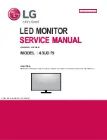
Page 1: ...Internal Use Only CHASSIS LM 6OB MODEL 43UD79 CAUTION BEFORE SERVICING THE CHASSIS READ THE SAFETY PRECAUTIONS IN THIS MANUAL SERVICE MANUAL LED MONITOR SERVICE MANUAL P NO MFL69406825 1702 REV00 ...

Page 2: ...nics Inc All rights reserved Only for training and service purposes CONTENTS 2 SAFETY PRECAUTIONS 3 SPECIFICATION 4 Firmware Upgrade Method 8 TROUBLE SHOOTING GUIDE 18 BLOCK DIAGRAM 14 EXPLODED VIEW 15 DISASSEMBLY 16 CONTENTS ...

Page 3: ... of electrical shock Leakage Current Cold Check Antenna Cold Check With the instrument AC plug removed from AC source connect an electrical jumper across the two AC plug prongs Place the AC switch in the on position connect one lead of ohm meter to the AC plug prongs tied together and touch other ohm meter lead in turn to each exposed metallic parts such as antenna terminals phone jacks etc If the...

Page 4: ... 6L RORU 2Q 6FUHHQ RQWURO XDO RQWUROOHU DFWRU FDOLEUDWLRQ 3 3 3 3 56 KHFNHG QSXW 0 1 0 0 KHFNHG 3 1 LVSOD 3RUW KHFNHG 86 1 3 3 9 VXSSRUW KHFNHG 3 3RZHU GHOLYHU 86 1 86 RZQVWUHDP SRUW TXLFN FKDUJLQJ VXSSRUW KHFNHG 4XLFN FKDUJLQJ VXSSRUW 86 GRZQVWUHDP 3RUW 8S WR 9 3 287 XGLR 5 KHFNHG 56 56 KHFNHG 3RZHU RUG HQJWK P 6KDSH DOO RXW HWDFKDEOH 7 SH P 5HIHU WR 6XIIL VWDQGDUG DQG SRZHU FRUG 7DEOH HLJKW NJ R...

Page 5: ...20 HLJKW NJ RORU ODFN NJ PSHGDQFH Ț Ț 211 725 Ț Ț a RKP a RKP 0 HQJWK P P 6KDSH HWDFKDEOH 7 SH P 3 1 RORU ODFN 5HIHU WR 20 HLJKW NJ RORU ODFN NJ PSHGDQFH Ț Ț 211 725 Ț Ț a RKP a RKP 3RZHU 3 QSXW a 9 a KHFNHG 3 1 XLOW LQ SRZHU 5HIHU WR 20 FFHVVRU R 1RW DSSOLHG SSO LQJ PRGXOH OLVW 3 1R 6SHFLILFDWLRQ KHFNHG Ě 8 02 8 LVSOD 5HIHU WR 20 0 4 5 LGE Internal Use Only Copyright LG Electronics Inc All rights...

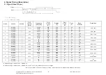
Page 6: ... 1600 24 80 96 1600 x 900 V Lines 60 00 1000 900 1 3 96 8 H Pixels 148 50 67 50 2200 1920 88 44 148 1920 x 1080 V Lines 60 1125 1080 4 5 36 9 H Pixels 241 5 88 79 2720 2560 48 32 80 2560 x 1440 V Lines 59 95 1481 1440 3 5 33 10 H Pixels 297 0 67 5 4000 3840 176 88 296 1 3840 x 2160 V Lines 30 2250 2160 8 10 72 11 H Pixels 594 0 135 4400 3840 176 88 296 2 3840 x 2160 V Lines 60 2250 2160 8 10 72 1 ...

Page 7: ... support mode Preset Mode Horizontal Frequency kHz Vertical Frequency Hz Remarks 480p 31 5 60 720p 45 0 60 1080p 67 5 60 2160p 135 60 7 LGE Internal Use Only Copyright LG Electronics Inc All rights reserved Only for training and service purposes ...

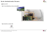
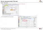
Page 8: ...nload monitor Firmware j G GYWXYGsnGl Gp UGh G G U v G G G G G ඖ How to do ISP Step1 Connect Realtek Jig to the monitor and PC Step2 Install like as attached file 5HDOWHN ULYHU QVWDOO XLGH j G Gt j G Gwj r and PC ...

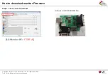
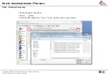
Page 9: ...How to download monitor Firmware j G GYWXYGsnGl Gp UGh G G U v G G G G G Step3 Run RTDToll Step4 ISP Icon Click ...

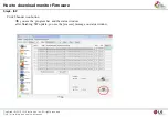
Page 10: ...How to download monitor Firmware j G GYWXYGsnGl Gp UGh G G U v G G G G G Step5 Check Access method LG Monitor JIG FTDIUsb LG Monitor JIG P N RAD33028001 ...

Page 11: ...How to download monitor Firmware j G GYWXYGsnGl Gp UGh G G U v G G G G G Step6 Option Check Enter Communication Option menu and then uncheck the Check ACK Set User data FE2P area select option ...

Page 12: ... to download monitor Firmware j G GYWXYGsnGl Gp UGh G G U v G G G G G Step7 Following below step 1 Check the Bank 0 checkbox 2 Click button 3 select the SW update file bin or hex and then click open button ...

Page 13: ...ad monitor Firmware j G GYWXYGsnGl Gp UGh G G U v G G G G G Step8 ISP Click Thunder icon button Î you see the progress bar and the status window after finishing SW update you see the success message on status window ...

Page 14: ...BLOCK DIAGRAM LGE Internal Use Only Copyright LG Electronics Inc All rights reserved Only for training and service purposes ...

Page 15: ... characteristics These parts are identified by in the Schematic Diagram and EXPLODED VIEW It is essential that these special safety parts should be replaced with the same components as recommended in this manual to prevent Shock Fire or other Hazards Do not modify the original design without permission of manufacturer IMPORTANT SAFETY NOTICE 200 400 510 500 900 910 920 940 810 520 800 120 121 330 ...

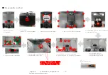
Page 16: ...ld screw 8ea fix 2 Speaker bracket L R screw 4ea fix 1 after LVDS cable connect attach EMI tape General drivers Tool Description 1 B cover assemble 1 Stand screw 4ea fix 1 Stand base thumb screw 1ea fix Waring use hand driver in the bottom of joystick cover screw 2ea Screw Torque 4 6kgf 16 Copyright LG Electronics Inc All rights reserved Only for training and service purposes ...

Page 17: ...ver 1 Disassemble EMI tape 2 Disassemble Speaker L R 3 Disassemble PCB bracket 1 Rear shield screw 8ea disassemble 2 Speaker bracket L R screw 4ea disassemble 1 Disassemble LVDS EMI tape 2 Disassemble LVDS cable 1 PCB screw 12ea disassemble General drivers Tool Description waring disassemble LVDS cable when rear shield up 17 Copyright LG Electronics Inc All rights reserved Only for training and se...

Page 18: ...ved Only for training and service purposes LGE Internal Use Only 1 NO POWER 5HSODFH 1 KHFN 3 9ROWDJH HYHO 9 KHFN 3RZHU FRQQHFWRU 2 5HSODFH 3RZHU RDUG 1 KHFN 2XWSXW 9ROWDJH HYHO 9 9 5HSODFH 5HFKHFN 1 KHFN ORFN 0 KHFN 2XWSXW 9ROWDJH HYHO 96 5HSODFH 5HFKHFN 1 5HSODFH ODVK 0HPRU ...

Page 19: ...rvice purposes LGE Internal Use Only 2 NO SCREEN ON 5HSODFH DEOH 1 0RGXOH DFN LJKW 2Q KHFN 5HSODFH 0DLQ 6FDOHU 1 1 KHFN 3DQHO 3RZHU 9 3 KHFN 2XWSXW 9 5HSODFH 5HFKHFN 1 KHFN 3DQHO ORFN 3 KHFN 5HSDLU 0DLQ 1 KHFN DEOH IRU DPDJH RU 2SHQ RQGXFWRUV KHFN ULYHU 3 5HSODFH 7 RQ RDUG RU 0RGXOH ...

Page 20: ...c All right reserved Only for training and service purposes LGE Internal Use Only 3 No Video y Gt G z GOpjXWWP j G G G p G G f j G qrYWWSYWXSYWYSwYW WG G G G G k y Gj u j GpYjG z OqrYWWSYWXSY WYSwYWW y Gk GlkpkG k u j Gk Gj G Gk G G v Gj ...

Page 21: ......

Reviews: