8 PLASMA TV
Introduction
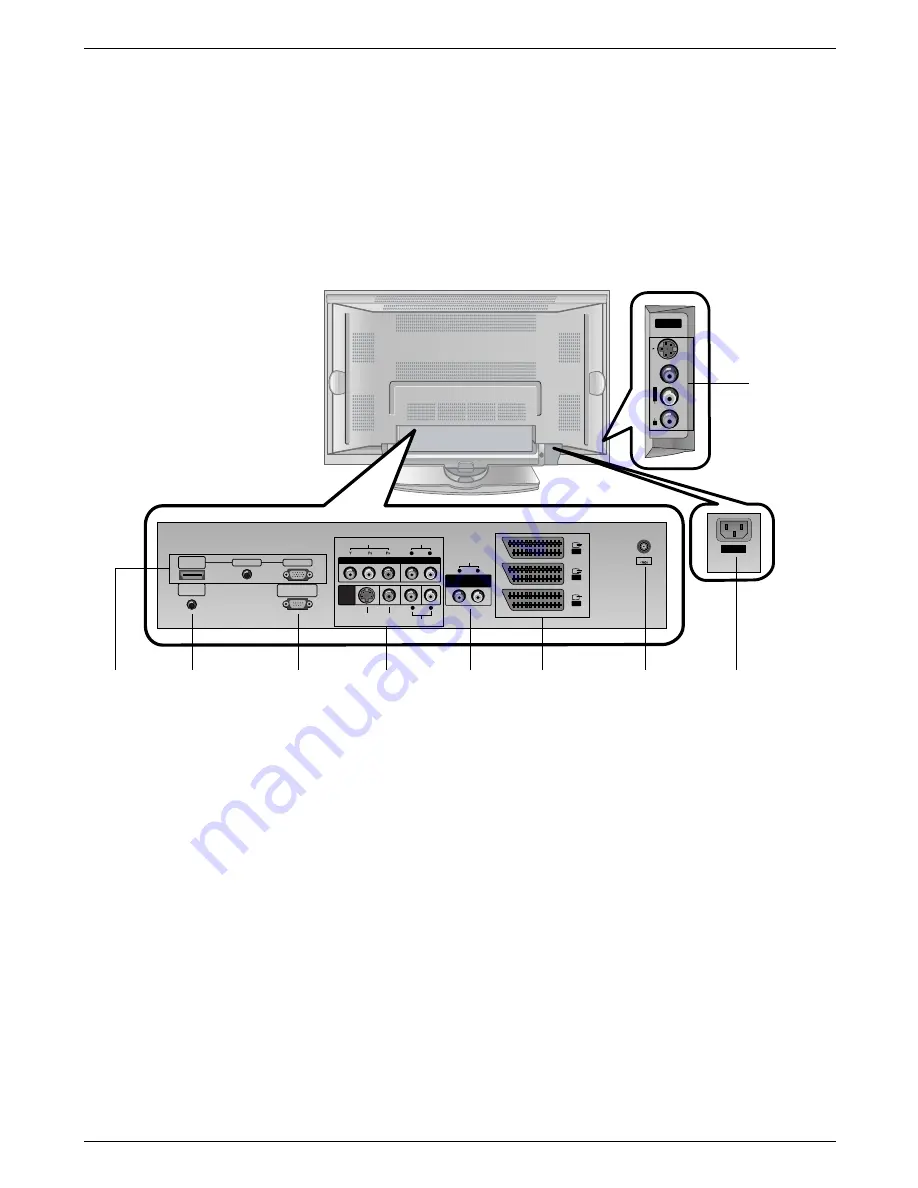
<Back Panel>
S-VIDEO
V
ID
E
O
A
U
D
IO
R
L/
M
O
N
O
A
AV5
V5
AC INPUT
Antenna
AUDIO
AUDIO
L
R
VIDEO
VIDEO
COMPONENT
COMPONENT
AUDIO
AUDIO
L
R
V
VARIABLE
ARIABLE
AUDIO OUT
AUDIO OUT
AUDIO
AUDIO
(MONO)
(MONO)
L
R
S-VIDEO
S-VIDEO VIDEO
VIDEO
A
AV4
V4
A
AV1
V1
A
AV2
V2
A
AV3
V3
HDMI/
DVI(VIDEO)
AUDIO INPUT
RGB INPUT
RS-232C INPUT
(CONTROL/SERVICE)
REMOTE
CONTROL
1. HDMI(DVI VIDEO) / AUDIO INPUT / RGB INPUT
Connect the monitor output socket of the PERSONAL COM-
PUTER, DVD or STB to this socket.
Note: If you want to use RGB/DVI audio, we strongly recom-
mend that you use the cable that has a core, or the EMI Filter
core along with separate cable.
2. REMOTE CONTROL
3. RS-232C INPUT(CONTROL/SERVICE) PORT
Connect to the RS-232C port on a PC.
4. COMPONENT INPUT
Connect DVD video outputs to Y, P
B
, P
R
of COMPONENT
INPUT and audio outputs to Audio sockets of AUDIO INPUT.
AUDIO/VIDEO IN SOCKETS (AV4)
Connect the audio/video out sockets of external equipment to
these sockets.
S-VIDEO/AUDIO IN SOCKETS
Connect the S-VIDEO out socket of an VCR to the S-VIDEO
socket.
Connect the audio out sockets of the VCR to the audio sock-
ets as in AV4.
5. VARIABLE AUDIO OUTPUT
6. EURO SCART SOCKET
Connect the euro scart socket of the VCR to these sockets.
Note:
a. If you want to use the EURO scart cable, you have to use
the signal shielded Euro scart cable.
b.
If the S-VIDEO(Y/C) signal is received through the Euro scart
socket 2 (AV 2), you must change to the
S-Video 2
(Y/C) mode.
7. ANTENNA INPUT
8. POWER CORD SOCKET
This Monitor operates on AC power. The voltage is indicated
on the Specifications page. Never attempt to operate the set
on DC power.
9. AUDIO/VIDEO INPUT (AV5)
S-VIDEO/AUDIO IN SOCKETS
1
4
2
3
6
7
5
8
9
- Shown is a simplified representation of the set.
- What is shown here may be somewhat different from your set.
- This manual explains the features available on the 42PX4R series.


