background image

25

Installation

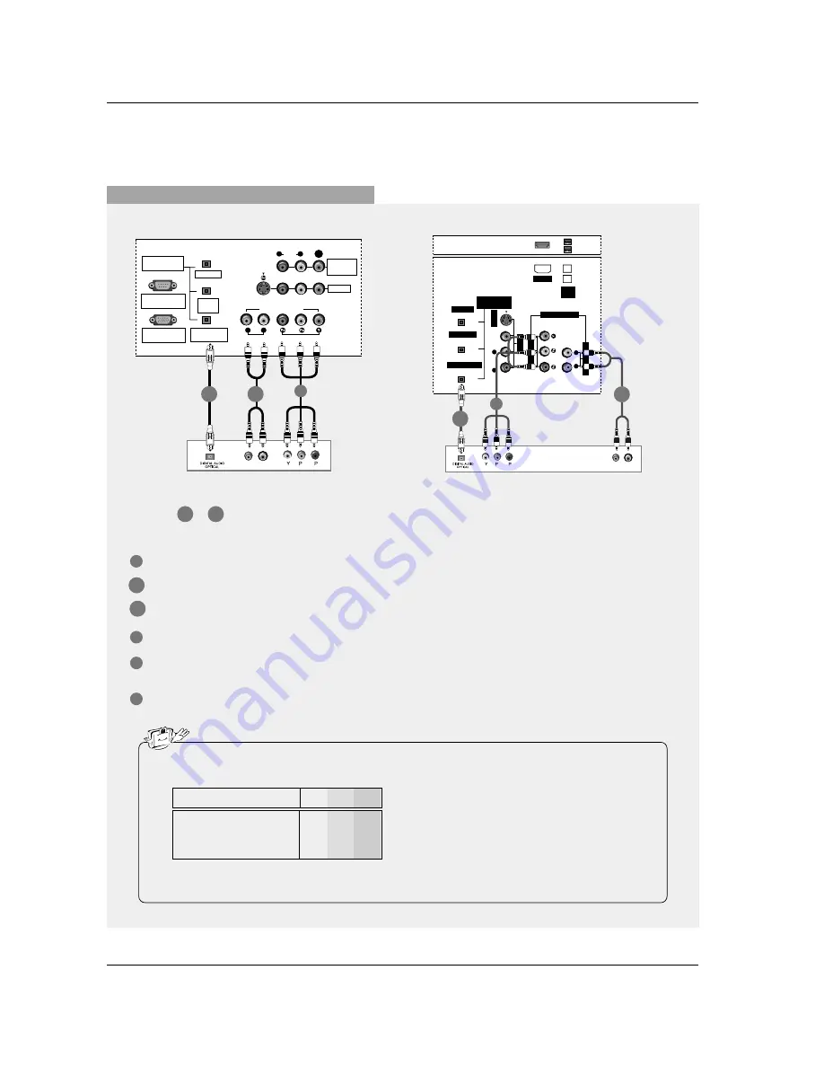
When connecting with a component cable

1

3

4

5

Connect the video outputs (Y, P

B

, P

R

)  of the DVD  to the 

COMPONENT1 VIDEO INPUT

jacks on the set.

Connect the audio outputs of the DVD to the 

COMPONENT1 AUDIO INPUT

jacks on the set.

Connect the optical audio output of the DVD to the 

DIGITAL AUDIO COMPONENT1 INPUT 

jack on the set.

Turn on the DVD player, insert a DVD.

Select 

Component 1 

input source with using the 

TV/VIDEO

button on the remote control.

- If connected to COMPONENT2 input, select 

Component 2 

input source.

Refer to the DVD player's manual for operating instructions.

Component Input ports

To get better picture quality, connect a DVD player to the component input ports as shown below.

• Digital Audio will not work for Component 2 input source.
• Digital Audio operation has priority if Digital Audio and AUDIO L/R are connected at the same time.

Y

P

B

P

R

Component ports on the TV

Y
Y
Y
Y

Pb

B-Y

Cb

P

B

Pr

R-Y

Cr

P

R

Video output ports 

on DVD player

B

R

(R) AUDIO (L)

DIGITAL AUDIO

(OPTICAL)

DVI

INPUT

COMPONENT1

INPUT

OUTPUT

VIDEO1

RGB INPUT

(PC/DTV INPUT)

RS-232C INPUT

(CONTROL/SERVICE)

AUDIO INPUT

AUDIO

(MONO)

VIDEO INPUT

COMPONENT1

R

L

R

L

S-VIDEO

MONITOR

OUT

VIDEO

DIGITAL AUDIO

(OPTICAL)

OUTPUT

VIDEO1

A

UDIO INPUT

VIDEO INPUT

RL

S-VIDEO

IEEE
1394

A

UDIO

VIDEO

(MONO)

RL

HDMI

DVI INPUT

COMPONENT1 INPUT

COMPONENT1

B

R

(R) AUDIO (L)

DVD

DVD

1

Select      or      , depending on your DVD connector.

2-1

2-1

2-1

2-2

2-2

1

2-1

2-2

2-2

32, 37, 42 inch TV Back

26 inch TV Back

Summary of Contents for 37LP1D

Page 1: ...number and serial number of the set See the label attached on the back cover and quote this information to your dealer when you require service P NO 3828TUL309D 0503 REV01 Printed in Korea OWNER S MANUAL MODELS 26LX1D 32LX1D 26LX2D 32LX2D 32LP1D 37LP1D 42LP1D Internet Home Page http www lge com http www lg ca TM ...

Page 2: ...erference in a residential installation This equipment generates uses and can radiate radio frequency energy and if not installed and used in accordance with the instructions may cause harmful interference to radio communications However there is no guarantee that interference will not occur in a particular installation If this equipment does cause harmful interference to radio or television recep...

Page 3: ...lowing issued United States patents 6 498 895 6 418 556 6 331 877 6 239 794 6 154 203 5 940 073 4 908 713 4 751 578 4 706 121 Use of the CableCARD TM TradeMark CableCARD TM is a trademark of Cable Television Laboratories Inc This digital television is capable of receiving basic analog digital basic and digital premium cable television program ming by direct connection to a cable system providing s...

Page 4: ...l near any heat sources such as radiators heat registers stoves or other apparatus including amplifiers that produce heat 9 Do not defeat the safety purpose of the polarized or grounding type plug A polarized plug has two blades with one wider than the other A grounding type plug has two blades and a third grounding prong The wide blade or the third prong is provided for your safety When the provi...

Page 5: ...t defects may be visible on the screen appearing as tiny red green or blue spots However they have no adverse effect on the monitor s performance Avoid touching the LCD screen or holding your finger s against it for long periods of time Doing so may produce some temporary distortion effects on the screen CAUTION concerning the Power Cord Most appliances recommend they be placed upon a dedicated ci...

Page 6: ...uide On Screen Notices Digital Cable Compatibility 4 5 Safety Instructions 8 Accessories 9 Controls Model Name 32 37 42LP1D 10 Connection Options Model Name 32 37 42LP1D 11 Controls Model Name 26 32LX1D 26 32LX2D 12 Connection Options Model Name 26LX1D 2D 13 Connection Options Model Name 32LX1D 2D 14 18 Remote Control Key Functions 19 Various Installation 20 How to use back cover 20 Swivel Stand 3...

Page 7: ...n and Sub Picture Sizes for Twin Picture 95 Swapping the PIP Twin Picture 95 POP Picture out of Picture Channel Scan Notes on Memory card 96 What is Memory Card 96 Precaution for Using the Memory Card 97 Insert Eject Memory Card 98 Supported Files Mode 98 Basic Operation JPEG File Viewing Options 99 Photo List OSD Display 99 Picture Selection and Popup menu MP3 Files Playing Operation 100 Music Li...

Page 8: ...the dealer from where you purchased the product 1 5V 1 5V TV INP UT TV VID EO VO L FL AS HB K C H PO W ER 1 2 3 4 5 6 7 8 0 9 AD JU ST RA TI O SW AP TI ME R PI P CH PI P CH PI P SA P CC M C EJ EC T FR EE ZE AU TO DE MO EZ PI C AP M EZ SO UN D PIP IN PU T AU DIO DA Y CA BL E ME NU MU TE PA GE PA GE FA V TV GU IDE VC R DA Y ST B EX IT 13 94 MA RK TV DV D MO DE INF O i EN TE R Remote Control Batterie...

Page 9: ...394 IEEE Power Standby Indicator Illuminates red when the TV is in standby mode When the TV is switched on blinks green and then illuminates green Remote Control Sensor TV GUIDE Button VOLUME F G Buttons CHANNEL E D Buttons Memory Card Slot For mode MENU Button ON OFF Button S VIDEO Input Audio Video Input 2 Logo Display Lamp Channel Display TV VIDEO Button DTV CADTV mode TV CATV DTV CADTV mode Vi...

Page 10: ...BLE AC IN MONITOR OUT VIDEO HDMI The HDMI port can receive video via High Definition Multimedia Interface HDMI or the Digital Visual Interface DVI Note An adapter or special cable is required to plug DVI into an HDMI port available at home theater or computer stores COMPONENT2 VIDEO AUDIO Input DIGITAL AUDIO OUTPUT DVI INPUT COMPONENT1 INPUT AUDIO VIDEO INPUT1 COMPONENT1 VIDEO AUDIO INPUT MONITOR ...

Page 11: ...shown may be somewhat different from your TV CH VOL VOL MENU MENU TV VIDEO TV GUIDE ON OFF ON OFF VOLUME F G Buttons Remote Control Sensor Power Standby Indicator Illuminates red when the TV is in standby mode When the TV is switched on blinks green and then illuminates green CHANNEL E D Buttons MENU Button ON OFF Button TV GUIDE Button TV VIDEO Button ...

Page 12: ...SERVICE PORT AUDIO INPUT VIDEO INPUT R L PC AUDIO INPUT REMOTE CONTROL S VIDEO CableCARD IEEE 1394 CABLE AC IN AUDIO VIDEO MONO R L HDMI DVI INPUT COMPONENT1 INPUT COMPONENT1 R MONO L VIDEO S VIDEO VIDEO AUDIO COMPONENT 2 VIDEO 2 COMPONENT2 VIDEO Input AUDIO Input VIDEO2 S VIDEO Memory Card Slot Formmmm mode DIGITAL AUDIO OUTPUT DVI INPUT COMPONENT1 INPUT AUDIO VIDEO INPUT1 COMPONENT1 VIDEO AUDIO ...

Page 13: ...ENT2 VIDEO Input AUDIO Input VIDEO2 S VIDEO Memory Card Slot Formmmm mode The HDMI port can receive video via High Definition Multimedia Interface HDMI or the Digital Visual Interface DVI Note An adapter or special cable is required to plug DVI into an HDMI port available at home theater or computer stores DIGITAL AUDIO OUTPUT DVI INPUT COMPONENT1 INPUT AUDIO VIDEO INPUT1 COMPONENT1 VIDEO AUDIO IN...

Page 14: ...V VIDEO Refer to p 17 External input modes rotate in regular sequence Antenna Cable Video1 2 Component 1 2 RGB DTV or RGB PC HDMI DVI Video 1 2 Component 1 2 input sources are linked automatically Only if these are connected EXIT Clears all on screen displays and returns to TV viewing from any menu 1394 Refer to p 36 41 Use it to operate the DVHS MicroMV camcorder and DSTB INFO Refer to p 93 When ...

Page 15: ...T RATIO SWAP TIMER PIP CH PIP CH PIP SAP CC M C EJECT FREEZE AUTO DEMO EZ PIC APM EZ SOUND PIP INPUT AUDIO DAY CABLE MENU MUTE PAGE PAGE FAV TV GUIDE VCR DAY STB EXIT 1394 MARK TV DVD MODE INFO i ENTER Mode Control Buttons Controls the Mode For further details see the Mode section DASH Used to enter a program number for multiple program chan nels such as 2 1 2 2 etc FLASHBK Returns to the last cha...

Page 16: ... mode SWAP Refer to p 95 Exchanges the main sub images in PIP Twin picture mode SAP Refer to p 79 Selects MTS sound Mono Stereo and SAP in analog mode Change the audio language in DTV mode EZ PIC Refer to p 75 Selects a factory preset picture mode depending on the view ing environment APM Refer to p 75 Concurrently compare with the Daylight Normal Night Time and Custom on the screen EZ SOUND Refer...

Page 17: ...onnected to Video 2 Video2 RGB DTV or RGB PC HDMI DVI You can also select Main Input in the SETUP menu Antenna Select it when watching the TV DTV Cable Select it when watching the CATV CADTV Video1 2 Select it when watching the VCR or external equip ment Component 1 2 Select it when using the DVD or the Digital set top box depend on connector RGB PC RGB DTV Select it when using PC or Digital set t...

Page 18: ...LE MENU MUTE PAGE PAGE FAV TV GUIDE VCR DAY STB EXIT 1394 MARK TV DVD MODE INFO i ENTER EZ Mute When you repeatedly press the MUTE button the sound mode is changed in turn Refer to the picture below Mute Sound is muted Mute EZ Mute A special mute mode to activate the closed caption automatically Mute Off Sound is enabled Note EZ Mute does not operate in Component RGB HDMI DVI modes EZ Mute 24 ...

Page 19: ...l Mounting Bracket Installation and Setup Guide Wall Mount Horizontal installation Desktop Pedestal Installation 4 inches 4 inches 4 inches 4 inches 4 inches 4 inches 4 inches 4 inches 4 inches 4 inches 4 inches 4 inches 4 inches 4 inches 4 inches 4 inches 4 inches 4 inches 4 inches 4 inches 4 inches 4 inches 4 inches 4 inches 4 inches 4 inches 4 inches For proper ventilation allow a clearance of ...

Page 20: ...T PC INPUT PC SOUND AV1 AV2 VIDEO L AUDIO R Reinstall the cover 4 Antenna LOOPTHROUGH UPGRADE PORT HDMI MONITOR OUT REMOTE CONTROL DVI INPUT PC INPUT PC SOUND AV1 AV2 VIDEO L AUDIO R Align the holes on the TV back panel with the protuberances on the back cover and insert 3 The TV can be conveniently swivelled on its stand 30 to the left or right to provide the optimum viewing angle Swivel Stand 32...

Page 21: ...ion if needed Cable TV Wall Jack RF Coaxial Wire 75 ohm Turn clockwise to tighten CABLE Analog and Digital TV signals provided on cable ANTENNA CABLE Analog and Digital TV signals provided on cable and antenna Cable TV Wall Jack RF Coaxial Wire 75 ohm Bronze Wire Bronze Wire Turn clockwise to tighten Antenna RF Coaxial Wire 75 ohm In a poor signal area to improve picture quality purchase and insta...

Page 22: ... R AUDIO L VIDEO 3 4 OUTPUT SWITCH ANT OUT ANT IN VIDEO1 AUDIO INPUT AUDIO MONO VIDEO INPUT COMPONENT1 R L R L S VIDEO MONITOR OUT VIDEO VCR VCR 32 37 42 inch TV Back 26 inch TV Back 32 37 42 inch TV Back 1 2 3 Connect the AUDIO VIDEO jacks between TV and VCR Match the jack colors Video yellow Audio Left white and Audio Right red Insert a video tape into the VCR and press PLAY on the VCR Refer to ...

Page 23: ...UT SWITCH ANT OUT ANT IN VCR VCR 1 1 1 2 2 2 3 4 Connect the S VIDEO output of the VCR to the S VIDEO input on the set The picture quality is improved compared to normal composite RCA cable input Connect the audio outputs of the VCR to the AUDIO input jacks on the set Insert a video tape into the VCR and press PLAY on the VCR Refer to the VCR owner s manual Select Video1 input source with using th...

Page 24: ...er to the DVD player s manual for operating instructions When connecting with a HDMI cable 1 2 3 Connect the HDMI output of the DVD to the HDMI jack on the set Select HDMI input source with using the TV VIDEO button on the remote control Refer to the DVD player s manual for operating instructions ANTENNA CableCARD IEEE 1394 CABLE HDMI HDMI DVD OUPUT HDMI DVD OUPUT AUDIO INPUT VIDEO INPUT R L Cable...

Page 25: ...re quality connect a DVD player to the component input ports as shown below Digital Audio will not work for Component 2 input source Digital Audio operation has priority if Digital Audio and AUDIO L R are connected at the same time Y PB PR Component ports on the TV Y Y Y Y Pb B Y Cb PB Pr R Y Cr PR Video output ports on DVD player B R R AUDIO L DIGITAL AUDIO OPTICAL DVI INPUT COMPONENT1 INPUT OUTP...

Page 26: ...s without an external digital set top box However if you do receive Digital signals from a digital set top box or other digital external device refer to the figure as shown below AC IN G LINK DIGITAL AUDIO OPTICAL DVI INPUT COMPONENT1 INPUT OUTPUT RGB INPUT PC DTV INPUT RS 232C INPUT CONTROL SERVICE PC AUDIO INPUT REMOTE CONTROL RGB DTV OUPUT R AUDIO L G LINK DIGITAL AUDIO OPTICAL OUTPUT VIDEO1 RG...

Page 27: ...V VIDEO button on the remote control If connected to COMPONENT2 input select Component 2 input source B R R AUDIO L DIGITAL AUDIO OPTICAL DVI INPUT COMPONENT1 INPUT OUTPUT VIDEO1 RGB INPUT PC DTV INPUT RS 232C INPUT CONTROL SERVICE AUDIO INPUT AUDIO MONO VIDEO INPUT COMPONENT1 R L R L S VIDEO MONITOR OUT VIDEO DIGITAL AUDIO OPTICAL OUTPUT VIDEO1 AUDIO INPUT VIDEO INPUT R L S VIDEO IEEE 1394 AUDIO ...

Page 28: ... AUDIO INPUT VIDEO INPUT R L CableCARD IEEE 1394 HDMI COMPONENT1 Digital Set top Box Digital Set top Box 1 1 TV can receive the video and audio signal simultaneously with using a HDMI cable If the digital set top box supports Auto HDMI function output resolution of the digital set top box will be auto matically set to 1280x720p If the digital set top box does not support Auto HDMI you need to set ...

Page 29: ...NTROL S VIDEO CABLE MONITOR OUT VIDEO IEEE 1394 HDMI R AUDIO L DIGITAL AUDIO OPTICAL DVI DTV OUTPUT G LINK DIGITAL AUDIO OPTICAL OUTPUT VIDEO1 RGB INPUT PC DTV INPUT RS 232C INPUT CONTROL SERVICE PORT AUDIO INPUT VIDEO INPUT R L PC AUDIO INPUT REMOTE CONTROL S VIDEO IEEE 1394 AUDIO VIDEO MONO R L HDMI DVI INPUT COMPONENT1 INPUT COMPONENT1 Digital Set top Box Digital Set top Box 1 2 1 2 2 1 2 1 2 2...

Page 30: ...ther end of the optical cable to the digital audio optical input on the audio equipment See the external audio equipment instruction manual for operation When connecting with external audio equipments such as amplifiers or speakers please turn the TV speakers off Refer to p 80 AC IN G LINK DIGITAL AUDIO OPTICAL DVI INPUT COMPONENT1 INPUT OUTPUT RGB INPUT PC DTV INPUT RS 232C INPUT CONTROL SERVICE ...

Page 31: ...or out When connecting with external audio equipments such as amplifiers or speakers please turn the TV speakers off Refer to p 80 CableCARD TM Setup To view the premium stations Insert the CableCARD TM received from Cable Service provider to CableCARD slot of TV as shown If the pairing information about this TV and the CableCARD is automatically displayed on the screen contact with Cable service ...

Page 32: ... the PC and the set Select RGB PC input source with using the TV VIDEO button on the remote control AC IN G LINK DIGITAL AUDIO OPTICAL DVI INPUT COMPONENT1 INPUT OUTPUT RGB INPUT PC DTV INPUT RS 232C INPUT CONTROL SERVICE PC AUDIO INPUT REMOTE CONTROL RGB PC OUPUT AUDIO AC IN RGB PC OUPUT AUDIO G LINK DIGITAL AUDIO OPTICAL OUTPUT VIDEO1 RGB INPUT PC DTV INPUT RS 232C INPUT CONTROL SERVICE PORT PC ...

Page 33: ...NT1 R L R L PC AUDIO INPUT REMOTE CONTROL S VIDEO CABLE MONITOR OUT VIDEO IEEE 1394 HDMI AUDIO DVI PC OUTPUT G LINK DIGITAL AUDIO OPTICAL OUTPUT VIDEO1 RGB INPUT PC DTV INPUT RS 232C INPUT CONTROL SERVICE PORT AUDIO INPUT VIDEO INPUT R L PC AUDIO INPUT REMOTE CONTROL S VIDEO IEEE 1394 AUDIO VIDEO MONO R L HDMI DVI INPUT COMPONENT1 INPUT COMPONENT1 PC PC If the PC has a DVI output and no HDMI outpu...

Page 34: ...vice center 6 Check the image on your TV There may be noise associated with the resolution vertical pattern contrast or brightness in PC HDMI DVI mode If noise is present change the PC or HDMI DVI mode to another resolution change the refresh rate to another rate or adjust the brightness and contrast on the menu until the picture is clear If the refresh rate of the PC graphic card can not be chang...

Page 35: ...lossary When RGB connect to PC input and select the RGB PC in Main Input this function is used When HDMI DVI connect to PC input and select HDMI DVI input this function is used In RGB DTV mode SIZE and PHASE is not available In HDMI DVI PC mode PHASE is not available After connecting RGB PC or HDMI DVI to PC input and checking the screen quality Press the ADJUST button and then use D D E E button ...

Page 36: ...Camcorder MicroMV Camcorder TV Connect the IEEE1394 Cable To operate the IEEE1394 these methods are available as shown below a TV DVHS b TV MicroMV Camcorder DVHS TV MicroMV Camcorder Generic Connect the IEEE1394 Cable Connect the IEEE1394 Cable Note When connecting the DVHS and the MicroMV Camcorder in case of showing input error on the MicroMV Camcorder window it s okay c TV DVHS MicroMV Camcord...

Page 37: ...ch It searches the program s start point and then plays On skip ping Search F FF F G GG G Pause II and Play G G are displayed on the Control Panel In some models it s not avail able to operate the Skipping IF FF F G GG GI function Depending on the connected equipment control panel may differ JVC HM DH40000K JVC HM DH40000U JVC HM DH5U MITSUBISHI HV HD1000 PANASONIC NV DH2 Supported DVHS List The o...

Page 38: ... Status Tape shape Icon Tape in or not Lock shape Icon Writable or not 7 MicroMV Camcorder Play Search Pause or Stop 8 Initializing Play Time Depending on the connected equipment control panel may differ The other DVHS device can work a basic operation SONY DCR IP 1 SONY DCR IP 5 SONY DCR IP 45 SONY DCR IP 210 Supported MicroMV Camcorder List TV Connect the IEEE1394 Cable 3 4 6 5 7 8 1 2 In camera...

Page 39: ...r 1 Synchronously connect the IEEE 1394 jack of the TV to the IEEE 1394 jack of the DVHS and the MicroMV Camcorder with IEEE 1394 Cable 2 Press the D D E E button to select device then press ENTER button to play it And then select ed device will be showed OSD ...

Page 40: ...device IEEE 1394 Cable 2 When watching the TV press the 1394 button and then D D E E buttons to select the DTV Link supported device and then use the ENTER but ton 3 Press the TV INPUT button to stop the IEEE1394 function DTV Link Producer TV Connect the IEEE1394 Cable W W How to play the DTV Link On a condition of connecting the IEEE 1394 you can control the DTV Link device while watching the OSD...

Page 41: ...not work properly When the same devices connect with 2 devices and over it s undesirable a LOOP Connection Connect the IEEE1394 Cable TV DVHS MicroMV Camcorder Connect the IEEE1394 Cable Connect the IEEE1394 Cable b When connecting the 4 devices and over the 1394 will not work properly ...

Page 42: ...PUT PC DTV INPUT RS 232C INPUT CONTROL SERVICE AUDIO INPUT AUDIO MONO VIDEO INPUT COMPONENT1 R L R L PC AUDIO INPUT REMOTE CONTROL S VIDEO CableCARD IEEE 1394 CABLE AC IN MONITOR OUT VIDEO HDMI S VIDEO OUT IN R AUDIO L VIDEO 3 4 OUTPUT SWITCH ANT OUT ANT IN ANTENNA G LINK DIGITAL AUDIO OPTICAL OUTPUT VIDEO1 RGB INPUT PC DTV INPUT RS 232C INPUT CONTROL SERVICE PORT AUDIO INPUT VIDEO INPUT R L PC AU...

Page 43: ...T AUDIO MONO VIDEO INPUT COMPONENT1 R L R L PC AUDIO INPUT REMOTE CONTROL S VIDEO CableCARD IEEE 1394 CABLE AC IN MONITOR OUT VIDEO HDMI ANTENNA G LINK DIGITAL AUDIO OPTICAL OUTPUT VIDEO1 RGB INPUT PC DTV INPUT RS 232C INPUT CONTROL SERVICE PORT AUDIO INPUT VIDEO INPUT R L PC AUDIO INPUT REMOTE CONTROL S VIDEO CableCARD IEEE 1394 CABLE AC IN AUDIO VIDEO MONO R L HDMI DVI INPUT COMPONENT1 INPUT COM...

Page 44: ...he air video signal In order to receive regular program listings please remember to do the following 1 Turn OFF your TV when it is not in use Do not unplug the power cord 2 If you have a Cable box connected leave it ON 3 If you have a VCR connected turn it OFF when not in use Do not unplug the power cord 4 If you have more than one Cable system in your area you may be prompted to select which Cabl...

Page 45: ...s ENTER button to display Screen 3 Option 2 If you selected Canada in Screen 1 you see the Postal Code screen You input characters by using the D D E E button and then the F F G G button to move to another field Press ENTER button to display Screen 3 2 Screen 1 Country This screen asks you the location of your TV Use the D D E E button to highlight a country Press ENTER button to display Screen 2 ...

Page 46: ...Screen 6 If you make any other choice you see Screen 7 5 Screen 6 Cable Box Tuning Channel Select the channel used for the cable box Press ENTER button to display Screen 7 6 Screen 7 Cable Box Configuration Diagram The diagram shows the correct way to install the G LINK TM Cable from the back of the device to the cable box Make sure the G LINK TM Cable is properly installed Press ENTER button to d...

Page 47: ...ructions and press ENTER button to display Screen 10 9 Screen 10 Cable Box Code Testing When testing is done Screen 11 displays automatically 10 Screen 11 Cable Box Tuned to Channel 9 If you select Yes you see Screen 12 If you select No a different code is tested in Screen 10 11 Many Cable Boxes require testing more than one code If you select Test this code again the same code is tested again in ...

Page 48: ...you see Screen 14 If you select No you see Screen 1 13 Screen 14 Congratulations Press ENTER button to display Screen 15 14 Screen 15 Is a VCR Connected If you select Yes you see Screen 16 If you select No you see Screen 21 15 If you selected No in Screen 3 then you must select Yes in this screen to receive a channel lineup and listings If you select No you see Screen 13 ...

Page 49: ...M Cable is properly installed Press ENTER button and you see Screen 17 16 Screen 17 VCR Brand Name Use the D D E E button to select the brand of the record ing device Press ENTER button and you see Screen 18 17 Screen 18 VCR Preparation Follow the on screen instructions and press ENTER button to display Screen 19 18 Screen 19 VCR Code Testing When testing is done Screen 20 displays automatically 1...

Page 50: ...nd setup and you see Screen 22 If it is not select No repeat setup process and you see Screen 1 21 Screen 22 Congratulations You have successfully completed Setup Press ENTER button and you see Screen 23 22 Screen 23 Helpful Information This screen tells you valuable information on using your Guide Press ENTER button to watch TV 23 Many VCRs require testing more than one code If you select Test th...

Page 51: ...ult setting options Channel lineup customization Help screens while in the Guide The screens displayed in the TV Guide On Screen system share many of the same components as shown in the following figure Screen Components Video Window displays TV video while the Guide is displayed Service Bar provides access to the 4 main Guide Services Current Service Label indented to indicate current Service dis...

Page 52: ...nless the highlight is on an odometer where these arrows change the odometer choice Pressing ENTER button from an odometer or number entry box moves the highlight to the default command button of that Panel Menu for example Schedule Reminder Pressing ENTER button from a highlighted command button executes the action and closes the Panel Menu e g Schedule Reminder Cancel Select Cancel to cancel any...

Page 53: ...e displayed in the Guide With Listings highlighted press the Info button to display a Help screen Press the Info button again to close the screen There may be times when the TV Guide On Screen system could display partial or no program listings The reasons for this include 1 Program schedule information was not provided to TV Guide On Screen 2 The transmission of the program listings was inter rup...

Page 54: ... E E button to highlight Movies Search lets you find shows by category Alphabetical Movies Sports Children Educational News Variety Series HDTV or by Keyword With Search highlighted press the INFO button to display a Help screen Press the INFO button again to close the screen Search ...

Page 55: ...ice Bar closes the menu changes no infor mation and returns to the Search Service Bar Tune to Channel exits the Guide and tunes to the channel of the highlighted show show airs in the future Note This option reads Watch Now if the show is currently airing Set Recording displays the Record Options menu from which you can set frequency start and end time etc Set Reminder displays the Remind Options ...

Page 56: ... New Search and press ENTER button 3 The Search Options menu is displayed 4 Highlight Category and use the F F G G button to select a category to search e g All HDTV Children Sports etc When finished use the E E button to highlight Enter Keyword 5 Highlight Enter Keyword and press ENTER button Then the keyboard is displayed 6 Use the D D E E F F G G button to highlight a character and press ENTER ...

Page 57: ...inder or tune to the channel as pre viously described The TV Guide On Screen system stores all the key words you create To edit or delete a keyword highlight the keyword and press the MENU buton A Search Options menu is displayed Go to Service Bar closes the menu changes no infor mation and returns to the Search Service Bar Edit Search displays the keyboard where you can change the keyword Delete ...

Page 58: ...set previously With Schedule highlighted press the INFO button to display a Help screen Press the INFO button again to close the screen An icon identifies the event type Schedule Once Regularly Daily Weekly Off Records the show one time Records the show every time the show airs on the same channel and starts at the same time Records the show each time the show airs on the same day of the week on t...

Page 59: ...ettings This option appears after you have completed the initial Guide Setup process Press ENTER button to display the Confirming Your Settings screen You see your current settings Choose one of the options press ENTER button and follow the on screen instructions After you initially complete Guide Setup you can make changes to Guide settings in the following areas Change System Settings Change Cha...

Page 60: ...Hide the channel is only displayed when pro gram information is available Press ENTER button to display the Channel Editor screen Then highlight a channel and press MENU button A Grid Options menu is displayed Highlight Go Back to Setup to close the menu change no information and return to the Setup Service Bar Or make changes and when finished press ENTER button to highlight Done Press ENTER butt...

Page 61: ...on when the INFO button is pressed while in the TV Guide On Screen system Choices are No only Small only Large only No Small No Large Small Large All Default All Automatic entry into the TV Guide On Screen sys tem Auto Guide when the TV is powered On Choices are On and Off Default On Highlight General Default Options and press the Menu key to display the General Default Options menu Highlight Go t...

Page 62: ...Remind Defaults Remind Default Options lets you set defaults for the following Power On the TV if Off when a Reminder is sched uled Choices are Yes and No Default No Automatically tune the TV to the channel TV must be On when a Reminder is scheduled Choices are Yes and No Default No When to display the reminder screen Choices are 30 seconds to 15 minutes early to 30 seconds to 15 minutes late to O...

Page 63: ...ow in Schedule There are 3 ways to set a show to Record 1 Using the Record Button on the Remote Press the Record button on the remote to record the show Once with current default settings Start and End recording On Time Each time you press the Record button you change the record frequency but not the default settings among Once default Regularly Off Weekly and then Cancel Note The proper Record ic...

Page 64: ...rding Highlight the Schedule Service label and press MENU button to display the Schedule Options menu Use the D D E E F F G G button to move through the options Use the number or the D D E E F F G G but ton to change the information as necessary Highlight New Manual Recording and press ENTER button to display the Record Options menu Current information i e date start and end times channel input is...

Page 65: ...nutes the notification screen automatically closes and completes the highlighted item Record Conflict A conflict message appears for the following reasons A show set to Record overlaps with any part of another show previously set to Record A show set to Record overlaps with a show previously set to auto tune Select one of these options Record anyway this show will override an existing show set to ...

Page 66: ...frequency next to the show title Highlight Cancel to close the menu change no information and return to the highlighted show You can set a show Reminder in Listings Search and Schedule or change Reminder settings for a show in Schedule There are 2 ways to set a show Reminder 1 From a Panel Menu Highlight a show and press MENU button to dis play the Episode Options menu Highlight Set Reminder and p...

Page 67: ...Press ENTER button again to close the menu You see a Remind icon for the select ed frequency next to the show title Note Manual reminder is listed by channel number Highlight Cancel to close the menu change no infor mation and return to the highlighted show Power On the TV if Off when a Reminder is sched uled Choices are Yes and No Default No Automatically tune the TV to the channel TV must be On ...

Page 68: ...ffect other Reminders you set Note If more than 2 reminders are set for the same time arrows appear on the Reminder screen Use the D D E E button to view the shows Remind Conflict A conflict message appears for the following reasons A show set with an Auto Tune Reminder has the same start time as an existing Auto Tune Reminder If you are using a cable box a show set with an Auto Tune Reminder over...

Page 69: ...anguage Selection Volume Adjustment Turning on the TV Channel Selection Press the MENU button and then use D D E E button to select the OPTION menu Press the G G button and then use D D E E button to select Language Press the G G button and then use D D E E button to select your desired language From this point on the on screen menus will be shown in the selected language Press EXIT button to retu...

Page 70: ... LOCK CABLE EZ Picture Contrast 85 Brightness 50 Color 50 Sharpness 50 Tint 0 Color Temperature Video Reset R G SETUP VIDEO AUDIO G TIME OPTION LOCK CABLE Audio Language EZ SoundRite EZ Sound Balance 0 Treble 50 Bass 50 Front Surround TV Speaker BBE L R SETUP VIDEO AUDIO TIME G OPTION LOCK CABLE Auto Clock Manual Clock Off Timer On Timer Sleep Timer Auto Off SETUP VIDEO AUDIO TIME OPTION G LOCK CA...

Page 71: ...ou want to add or delete Press the ENTER button to add or delete for the channel number Press EXIT button to return to TV viewing or press MENU button to return to the previous menu 1 2 3 4 5 6 SETUP VIDEO AUDIO TIME OPTION LOCK CABLE Previous MENU EZ Scan G Manual Scan Channel Edit DTV Signal Channel Label Main Input Sub Input Input Label Set ID Selection G or leads you to the EZ scan screen ANTE...

Page 72: ...system Setup cable channels CATV or CADTV will not be editable by Channel Edit Instead use the cable box s Channel Edit if avail able Channel Edit Press the MENU button and then use D D E E button to select the SETUP menu Press the G G button and then use D D E E button to select Channel Edit Press the G G button You will now see a screen filled with channel num bers and a preview picture Use D D ...

Page 73: ...s EXIT button to return to TV viewing or press MENU button to return to the previous menu 1 2 3 4 Press the MENU button and then use D D E E button to select the SETUP menu Press the G G button and then use D D E E button to select Channel Label Press the G G button You will now see a screen filled with Labels and a preview screen Use the CH D D E E button to select a channel to Label Use D D E E ...

Page 74: ...tton to select Input Label Press the G G button and then use D D E E button to select the source Video1 2 Component1 2 RGB or HDMI DVI Press the F F G G button to select the label Press EXIT button to return to TV viewing or press MENU button to return to the previous menu 1 2 3 4 5 SETUP VIDEO AUDIO TIME OPTION LOCK CABLE Previous MENU EZ Scan Manual Scan Channel Edit DTV Signal Channel Label Mai...

Page 75: ...able Press the EZ PIC button repeatedly to select the picture appear ance setup option as shown below Custom your own settings Daylight Normal Night Time Movie Video Game and Sports You can also adjust EZ Picture in the VIDEO menu Press the EXIT button to save and return to TV viewing 1 2 Press the APM button at once The screen is divided to 4 split Press the D D E E F F G G button to navigate 4 E...

Page 76: ... to select Video Reset Press the G G button to reset the Video menu options to original values 1 2 3 V Video Menu Options Continued ideo Menu Options Continued Press the MENU button and then use D D E E button to select the VIDEO menu Press the G G button and then use D D E E button to select the desired pic ture option Contrast Brightness Color Sharpness or Tint Press theG G button and then use F...

Page 77: ...s the MENU button and then use D D E E button to select the AUDIO menu Press the G G button and then use D D E E button to select Audio Language Press the G G button and then use D D E E button to select English Spanish or French Press EXIT button to return to TV viewing or press MENU button to return to the previous menu 1 2 3 4 Press the MENU button and then use D D E E button to select the AUDI...

Page 78: ...t the appropriate sound setup as shown below Custom your own settings Normal Stadium News Music and Theater You can also adjust EZ Sound in the AUDIO menu Press EXIT button to save and return to TV viewing 1 2 Press the MENU button and then use D D E E button to select the AUDIO menu Press the G G button and then use D D E E button to select the desired sound option Balance Treble or Bass Press th...

Page 79: ... press the SAP button Mono Stereo or SAP appear in turn If other languages available on the digital signal select them with the SAP button Press EXIT button to save and return to TV viewing 1 2 Mini Glossary SRS TruSurround XT Takes advantage of any multi channel format without needing to add extra speakers or equipment Dialog clarity bass enrichment and the addition of stereo audio enhancement th...

Page 80: ...On Press the MENU button and then use D D E E button to select the AUDIO menu Press the G G button and then use D D E E button to select TV Speaker Press the G G button and then use D D E E button to select Off or On Press EXIT button to return to TV viewing or press MENU button to return to the previous menu 1 2 3 4 SETUP VIDEO AUDIO TIME OPTION LOCK CABLE Previous MENU Audio Language EZ SoundRit...

Page 81: ...n and then use D D E E button to select Manual Clock Press the G G button and then use F F G G button to select either the year date or time option Once selected use the D D E E button to set the year date and time options Press EXIT button to return to TV viewing or press MENU button to return to the previous menu 1 2 3 4 SETUP VIDEO AUDIO TIME OPTION LOCK CABLE Previous MENU Auto Clock G Manual ...

Page 82: ...ess the G G button and then use D D E E button to set the minutes For only On Timer function Press the G G button and then use D D E E button to select the channel at turn on Press the G G button and then use D D E E button to set the sound level at turn on Press EXIT button to return to TV viewing or press MENU button to return to the previous menu 1 2 3 4 5 6 7 SETUP VIDEO AUDIO TIME OPTION LOCK...

Page 83: ...n and then use D D E E button to select Off or On Press EXIT button to return to TV viewing or press MENU button to return to the previous menu 1 2 3 4 SETUP VIDEO AUDIO TIME OPTION LOCK CABLE Previous MENU Auto Clock Manual Clock Off Timer On Timer Sleep Timer Auto Off G Off On If set to On and there is no input signal the TV turns off automatically after 10 minutes SETUP VIDEO AUDIO TIME G OPTIO...

Page 84: ...Selects the proper picture proportion to match the source s image 4 3 4 3 16 9 16 9 4 3 Choose 4 3 when you want to view a picture with an original 4 3 aspect ratio with black bars appearing at both the left and right sides 16 9 Choose 16 9 when you want to adjust the picture horizontally in a lin ear proportion to fill the entire screen Horizon Choose Horizon when you want to adjust the picture i...

Page 85: ...3 2 Mode G Caption Caption Text Caption Option Language Auto Demo Logo Light Off On Caption Press the MENU button and then use D D E E button to select the OPTION menu Press the G G button and then use D D E E button to select Caption Press the G G button and then use D D E E button to select Off or On Press EXIT button to return to TV viewing or press MENU button to return to the previous menu 1 ...

Page 86: ...ess EXIT button to return to TV viewing or press MENU button to return to the previous menu 1 2 3 4 SETUP VIDEO AUDIO TIME OPTION LOCK CABLE Previous MENU Aspect Ratio Cinema 3 2 Mode Caption Caption Text G Caption Option Language Auto Demo Logo Light English Spanish French SETUP VIDEO AUDIO TIME OPTION G LOCK CABLE Aspect Ratio Cinema 3 2 Mode Caption Caption Text Caption Option Language Auto Dem...

Page 87: ...the opacity for the background color Edge Type Select an edge type Edge Color Select a color for the edges Press EXIT button to return to TV viewing or press MENU button to return to the previous menu 1 2 3 4 5 SETUP VIDEO AUDIO TIME OPTION LOCK CABLE Previous MENU Aspect Ratio Cinema 3 2 Mode Caption Caption Text Caption Option G Language Auto Demo Logo Light Style Custom Size A Standard Font Fon...

Page 88: ...ight Press the G G button and then use D D E E button to select Off or On Press EXIT button to return to TV viewing or press MENU button to return to the previous menu 1 2 3 4 Press the FREEZE button in 720p or 1080i modes Use the D D E E F F G G buttons to select the screen section to be magnified To return to normal viewing press the FREEZE button again 1 2 3 SETUP VIDEO AUDIO TIME OPTION LOCK C...

Page 89: ...s strongly cautioned R Restricted NC 17 No one 17 and under admitted X Adult only If you set PG 13 G and PG movies will be avail able PG 13 R NC 17 and X will be blocked Ratings for Television programs including made for TV movies TV G General audience TV PG Parental guidance suggested TV 14 Parents strongly cautioned TV MA Mature audience only TV Y All children TV Y7 Children 7 years older TV Rat...

Page 90: ... hooked up W W For USA Movie Rating MPPA Blocks movies according to the movie rat ings limits specified so children cannot view certain movies You can set the ratings limit by blocking out all the movies with the rat ings above a specified level Keep in mind that the movie ratings limit only applies to movies shown on TV not TV programs such as soap operas TV Rating Children Prevents children from...

Page 91: ...n to select the CABLE menu Press the G G button and then use D D E E button to select to select your desired item Press the G G button Press EXIT button to return to TV viewing 1 2 3 4 SETUP VIDEO AUDIO TIME OPTION LOCK CABLE Previous MENU SA CableCARD Diag Screen G SA CableCARD Host ID Screen CableCARD tm Message In order to start service for this device please contact customer service at Ph 1 86...

Page 92: ...the picture 3 above Insert the CableCARD TM The TV receive a new cable channel list It takes about 2 3 minutes to gather the cable channel list after inserting the CableCARD TM It will occasionally will take longer 1 2 SETUP VIDEO AUDIO TIME OPTION LOCK CABLE Previous MENU EZ Scan G Manual Scan Channel Edit DTV Signal Channel Label Main Input Sub Input Input Label Set ID Selection G or leads you t...

Page 93: ... S V 6 55AM DTV 2 1 CC 4 3 Program title Program start time Banner information Program progress bar Program finish time Present time Day Month Year The original aspect ratio of the video is 4 3 The original aspect ratio of the video is 16 9 wide The video resolution is 720x480i The video resolution is 720x480p The video resolution is 1280x720p The video resolution is 1920x1080i Multilingual The pr...

Page 94: ...button to select a channel for the sub picture You can t select DTV for main and sub picture simultaneously PIP lets you view 2 different inputs sources on your TV screen at the same time One source will be large and the other source will show a smaller inset image Twin Picture mode splits the screen into 2 allowing 2 picture sources to be shown on the TV screen at the same time Each source is giv...

Page 95: ...el search before using POP mode When Sub pictures are changed from the TV DTV to CATV CADTV in POP mode it may make a noise from the Tuner switch 1 Press the PIP button to activate the POP mode while in PIP mode Channel selection Use F F button to enlarge the selected channel being searched on the PIP screen to shift it for viewing on the Main screen PIP selection Use D D E E button to select one ...

Page 96: ...off while using the memory card loading or erasing Don t eject the memory card while using the it Otherwise it may cause data loss or card damage Only Insert one card to each slot To prevent a change or loss for stored data don t misuse the TV or don t let static electricity or electrical noise for TV This Company takes no responsibility for problems such as the damage or malfunction that occurs w...

Page 97: ...e card from the slot Do not insert or eject a card in one slot while the card in the other slot slot 1 or slot 2 is in use the product may run abnormally Before you remove the memory card from the slot don t forget to press the M C EJECT button on the remote con trol or the memory card may be damaged i Memory Card1 Memory Card2 Cancel Select a memory card you want to eject Use the specified card b...

Page 98: ...ecure Digital 1GB MMC MultiMedia Card 1GB MS Memory Stick 128MB MS Pro Memory Stick Pro 1GB SMC Smart Media Card 128MB xD Extream Digital Picture Card 512MB Music File MP3 When you plug the Memory Card this screen is displayed automatically Basic Operation When you plug a memory card or press the button the above screens will be displayed Note In 30 seconds later Loading message is disappeared Ins...

Page 99: ...ly the marked ones If no photo is marked you can view or slideshow all photos in the folder Use D D E E F F G G button to navigate the appropriate thumbnail photos then press the ENTER button to show the PopUp menu View See the selected item to the full screen View state change to slide show state by pressing the PLAY G G button Slide Show Start a slide show with all photos in the folder The slide...

Page 100: ...copyright restrictions Playback of these files may not be sup ported by this model MP3 Files Playing Operation MP3 Files Playing Operation Music List OSD Display Marked MP3 file number Current Playing Time Total Playing Time Current file number Total file number Card type Direct Buttons Folder List G G Play II Pause A A Stop Usable Card memory ...

Page 101: ...gate the appropriate music titles then press the ENTER button to set the pop up menu Play Play the selected music Stop Play Stop the play Play With Photo Start playing the selected music by turns and then move to the Photo List Mark All Mark all music titles in the folder Unmark All Unmark all marked music Cancel Hide the pop up menu Repeatedly press EXIT button to return to TV viewing or press bu...

Page 102: ...trol system and control the Monitor s functions externally Connect the serial port of the control device to the RS 232C jack on the TV back panel RS 232C connection cables are not supplied with the TV T Type of Connector D Sub 9 Pin Male ype of Connector D Sub 9 Pin Male RS 232C Configurations RS 232C Configurations External Control Device Setup External Control Device Setup RS 232C Setup RS 232C ...

Page 103: ...ent The Monitor transmits ACK acknowledgement based on this format when receiving normal data At this time if the data is data read mode it indicates present status data If the data is data write mode it returns the data of the PC computer Command2 Set ID OK Data x Error Acknowledgement The Monitor transmits ACK acknowledgement based on this format when receiving abnormal data from non viable func...

Page 104: ... on k e Set ID Data Cr Acknowledgement e Set ID OK Data x 03 Aspect Ratio Command2 c Main picture format G To adjust the screen format You can also adjust the screen format using the RATIO button on remote control or in the Option menu Transmission k c Set ID Data Cr Acknowledgement c Set ID OK Data x 04 Screen Mute Command2 d G To select screen mute on off Transmission Data 0 Screen mute off Pict...

Page 105: ...ust sharpness in the Video menu Transmission 11 Sharpness Command2 k Data Min 0 Max 64 Refer to Real data mapping See page 104 k k Set ID Data Cr Acknowledgement k Set ID OK Data x 12 OSD Select Command2 l G To select OSD On Screen Display on off Transmission k l Set ID Data Cr Acknowledgement Data 0 OSD off 1 OSD on l Set ID OK Data x 15 PIP Position Command2 q G To select sub picture position fo...

Page 106: ...a 00 23 xx xx xx xx 01 attribute 0x01 main picture two part it s not mandatory using physical channel NTSC cable xx data don t care major and minor channel number in case analog channel tuning 2 Digital channel ATSC air channel number don t know physical channel major 30 minor 3 sub picture Command ma 00 xx 00 1E 00 03 A2 attribute 0xA2 sub picture two part not using physical channel ATSC air xx d...

Page 107: ...t the input source for sub picture in PIP mode Transmission x y Set ID Data Cr Acknowledgement y Set ID OK NG Data x DTV Antenna 00 DTV Cable 01 Analog Antenna 10 Analog Cable 11 Video 1 20 Video 2 21 Component 1 40 Component 2 41 RGB DTV 50 RGB PC 60 HDMI DVI 90 DATA Hex INPUT DTV Antenna 00 DTV Cable 01 Analog Antenna 10 Analog Cable 11 Video 1 20 Video 2 21 DATA Hex INPUT Data Structure Data St...

Page 108: ...ode Data code Data code TC Tf T1 C0 Carrier frequency FCAR 1 TC fOSC 12 Duty ratio T1 TC 1 3 Repeat frame C1 C2 C3 C4 C5 C6 C7 C0 C1 C2 C3 C4 C5 C6 C7 D0 D1 D2 D3 D4 D5 D6 D7 D0 D1 D2 D3 D4 D5 D6 D7 Repeat code 9 ms 4 5 ms 0 55 ms 9 ms 2 25 ms G Bit description G Frame interval Tf The waveform is transmitted as long as a key is depressed Bit 0 Tf Tf Tf 108ms 455KHz 0 56 ms 0 56 ms 1 12 ms Bit 1 2 ...

Page 109: ... TV Input Selection Discrete IR Code Video1 Input Selection Discrete IR Code Video2 Input Selection Discrete IR Code Component1 Input Selection Discrete IR Code Component2 Input Selection Discrete IR Code RGB PC Input Selection Discrete IR Code RGB DTV Input Selection Discrete IR Code HDMI DVI Input Selection Discrete IR Code Only 4 3 Mode Discrete IR Code Only 16 9 Mode Discrete IR Code Only Zoom...

Page 110: ...hile illuminating on the selected component Test the POWER button to see if the component responds properly If not the remote requires pro gramming to operate the device Turn on the component to be programmed then press the correspond ing MODE button on the remote control Press the MENU and MUTE buttons simultaneously for 2 seconds the button selected component lights on the remote control If you ...

Page 111: ... SEARS 003 008 009 010 013 014 017 020 031 042 073 081 101 SHARP 031 054 149 SHINTOM 024 SONY 003 009 031 052 056 057 058 076 077 078 149 SOUNDESIGN 034 STS 013 SYLVANIA 031 033 034 059 067 SYMPHONIC 034 TANDY 010 034 TATUNG 039 043 TEAC 034 039 043 TECHNICS 031 033 070 TEKNIKA 019 031 033 034 101 THOMAS 034 TMK 006 TOSHIBA 008 013 042 047 059 082 112 131 TOTEVISION 040 101 UNITECH 040 VECTOR RESE...

Page 112: ...s Brand Codes Brand Codes Brand Codes Brand Codes Brand Codes Brand Codes Brand Codes AIWA 014 028 070 096 125 129 139 229 230 AKAI 163 ANAM 003 014 017 023 059 106 189 216 217 235 236 BURMECTER 252 CARVER 086 CLARION 199 DAEWOO 027 053 060 084 102 148 198 221 DENON 015 075 130 143 FANTASIA 071 FINEARTS 022 FISHER 089 099 LG GOLDSTAR 001 021 024 029 087 107 108 110 190 191 192 210 211 212 239 HAIT...

Page 113: ...ncing problems tune to another station Station signal is weak reorient antenna to receive weaker station Check for sources of possible interference Lines or streaks in pictures Check antenna Change the direction of the antenna Check whether the product is turned on Try another channel The problem may be with the broadcast Is the power cord inserted into wall power outlet Check your antenna directi...

Page 114: ...on or off and does not indicate a fault with the product No output from one of the speakers Adjust Balance in menu option Screen color is unstable or single color Check the signal cable Reinstall the PC video card The signal is out of range There is a problem in PC mode Only PC mode applied Adjust resolution horizontal frequency or vertical frequency Check it whether the signal cable is connected ...

Page 115: ... the Cabinet Cleaning the Cabinet Extended Extended Absence Absence Maintenance Maintenance Product Specifications Product Specifications The specifications shown above may be changed without prior notice for quality improvement MODEL Width inches mm Height inches mm Depth inches mm Weight pounds kg Power requirement Television System Program Coverage External Antenna Impedance 31 787 7 20 510 7 6...

Page 116: ......

Reviews: