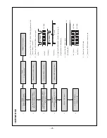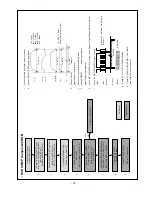
11-2. Adjustment of White Balance
O
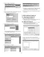
Operate the Zero-calibration of the CA-210, then attach
sensor to PDP module surface when you adjust.
O
Manual adjustment is also possible by the following sequence.
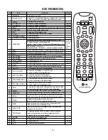
(1) HEAT RUN at least 30 minutes by pressing the Power only
Key on the Service Remote Control and adjust.
(2) After attaching sensor to center of screen, select ‘White-
Balance’ of ‘Ez - Adjust’ by pressing the ADJ KEY on the
Service R/C. Then enter adjustment mode by pressing the
Right KEY (
G
). This time white pattern is displayed.
(3) Adjust the Hight Light using R Gain/G Gain(Cool).
Adjust the Hight Light using G Gain/R Gain(Medium).
Adjust the Hight Light using G Gain/B Gain(Warm).
(R Gain: 192, B Gain 192, R-Cut/G-Cut/B-Cut: 64 Fix.)
(4) Adjust using /- KEY.
(5) After adjustment is complete, exit the adjustment mode by
pressing the ADJ KEY.
High Level: 216gray
[Cool]
X; 0.278±0.015 Y; 0.279±0.015
Color temperature: 11000°K±1000°K
dUV: -3dUV
[Medium]
X; 0.287±0.015 Y; 0.289±0.015
Color temperature: 9300°K±1000°K
dUV: -3dUV
[Warm]
X; 0.314±0.015 Y; 0.318±0.015
Color temperature: 6500°K±1000°K
dUV: -3dUV
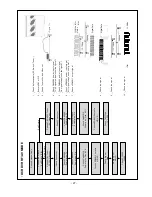
12. Video(uPD)-Set
Adjustment for reduce color difference Main/Sub screen of RF
or Video signal.
12-1. Adjustment
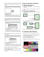
(1) Connection the Video Signal Generator(Master) to the TV
AV Input terminal.
After input pattern(Model: 201(NTSC-M), Pattern: 32(100%
color Bar), pressing the ‘Rev’ button and appear as below
figure
(2) After receive signal, confirm the signal receiving.
And Enter the ‘EZ-ADJUST’ by pressing the ADJ Key on
the Service R/C.
Select ‘5. Video(UPD)-Set’ and enter the adjustment mode
by pressing the right key (
G
).
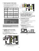
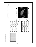
(3) When enter the adjustment mode, displayed the TV 2CH
SPLIT Screen automatic at picture and appear as below
figure.
(4) When the automatic adjustment is over, 'RF Configuration
Success’ is displayed. If the adjustment has errors, 'Video
Configuration Error’ is displayed.
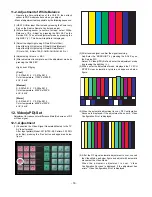
(5) After the RF signal automatic adjustment is over, convert
the Video Mode as below figure and adjust with automatic
movement the Video Mode.
When the automatic adjustment is over, 'Video
Configuration Success’ is displayed. If the adjustment has
errors, 'Video Configuration Error’ is displayed.
- 16 -
Summary of Contents for 37LB1D-UB
Page 24: ... 24 DCR DVR NO OSD ...
Page 26: ... 26 DCR DVR RF AV MODE ...
Page 30: ... 30 Component RGB HDMI DVI ...
Page 33: ... 33 DCR DVR DTV CADTV ...
Page 42: ... 42 Common sound out ...
Page 53: ... 53 EXPLODED VIEW 010 051 052 020 060 070 120 110 040 090 100 130 140 080 030 ...
Page 76: ......
Page 77: ......
Page 78: ......
Page 79: ......
Page 80: ......

