- 11 -
ADJUSTMENT INSTRUCTION
1. Application Object
These instructions are applied to all of the PDP TV, PA61A.
2. Notes
(1) Because this is not a hot chassis, it is not necessary to use
an isolation transformer. However, the use of isolation
transformer will help protect test equipment.
(2) Adjustments must be done in the correct order.
(3) The adjustments must be performed in the circumstance of
25±5°C of temperature and 65±10% of relative humidity if
there is no specific designation.
(4) The input voltage of the receiver be must kept 110V, 60Hz
when adjusting.
(5) The receiver must be operational for about 15 minutes
prior to the adjustments.
O
Preliminary action is applied to the test for afterimage
discharge detection, and 100% FULL WHITE PATTERN
must be operated automatically.
O
Test for afterimage discharge detection
1) After pressing Power Only key(only operating by
pressing Power Only key), Full Test Pattern(2 min
30sec) --> Full Black Pattern(30sec) --> After this state,
Full White Pattern is displayed.
(but you must preset the program for Full White State
when you press the Main Power Off/On)
2) Pattern Mode is deselected by pressing CH +/-, Exit Key.
[ Set is activated HEAT-RUN without signal generator in this
mode.
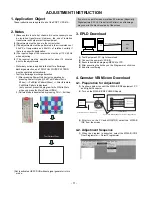
3. EPLD Download
(1) Test Equipment: PC, Jig for download
(2) Connect the power of VSC B/D.
(3) Execute download program(iMPACK) of PC.
(4) After executing the hot key on the Programmer, click icon
(5) End after confirming
4. Gemstar VBI Micom Download
4-1. Preparation for Adjustment
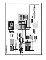
(1) As shown below, connect the MPLAB ICD2 equipment, PC
and Digital Connector.
(2) Turn on the MPLAB ICD2 POWER Supply.
(3) After turn on the PC and MONITOR, select the ‘MPLAB
IDE’ from the screen.
4-2. Adjustment Sequence
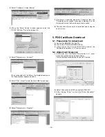
(1) When the program is executed, select the MPLAB ICD2
from Programmer -> Select Programmer .
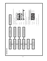
Test Pattern 2min 30sec
Test Pattern 30sec
If you turn on a still screen more than 20 minutes (Especially
Digital pattern(13 CH), Cross Hatch Pattern), an afterimage
may occur in the black level part of the screen.
PC
VSC
B/D
+13V
<Digital Board>
Connect the MPLAB ICD2 and connector of Digital Board
Connect the RS-232 or USB Cable
GND
Data
Summary of Contents for 37LB1D-UB
Page 24: ... 24 DCR DVR NO OSD ...
Page 26: ... 26 DCR DVR RF AV MODE ...
Page 30: ... 30 Component RGB HDMI DVI ...
Page 33: ... 33 DCR DVR DTV CADTV ...
Page 42: ... 42 Common sound out ...
Page 53: ... 53 EXPLODED VIEW 010 051 052 020 060 070 120 110 040 090 100 130 140 080 030 ...
Page 76: ......
Page 77: ......
Page 78: ......
Page 79: ......
Page 80: ......

