background image

55

206-4186

Troubleshooting (Cont.)

Commercial Mode Check / FTG Operation Troubleshooting

TV turned 

ON?

Yes

No

Press 

POWER on 

Installer Remote.

TV is not in Commercial 

Mode. Call Technical 

Support for assistance.

TV is in

Commercial Mode.

No

On-screen 

menu display 

no longer 

toggles?

Yes

Press MENU repeatedly  

as if to access the 

Installer Menu.

Function 

Menu 

on display?

Leave the TV set ON, 

and press MENU on the 

Installer Remote.

No

TV is in

Commercial Mode.

Yes

Plug into AC 

Power outlet.

TV 

connected 

to AC 

Power?

Bad

TV

No

Yes

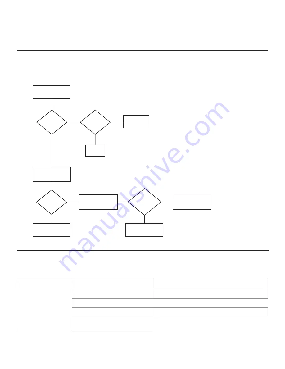
Commercial Mode Check 

Use this flowchart to determine whether the TV is currently in Commercial Mode.

FTG Operation Troubleshooting 

The following table provides troubleshooting information for when the EBL is configured in the FTG Mode of operation.

Symptom

Possible Cause(s)

Solution(s)

Communication Error 

(“Communications 

Timeout”)

Cable(s) not connected.

Check and connect communication cables.

TV not powered.

Check/connect the TV power cord.

TV not turned ON. 

TV needs to be turned ON (default FTG Mode).

Wrong COM  

(communication) port.

In the FTG Device Configuration Application, select the  

correct COM port for the cable being used.

Summary of Contents for 26LD340H

Page 1: ...ial Mode Setup Guide Note Selected features shown in this guide may not be available on all models Lodging Guest Interactive Pro Centric TVs Copyright 2011 LG Electronics U S A Inc P N 206 4186 Rev B 26LD320H 32LD320H 37LD320H 42LD320H 32LD325H 37LD325H 26LD340H 32LD340H 37LD340H 42LD340H 26LD345H 32LD345H 37LD345H 42LD345H ...

Page 2: ...the cable entry as practical REGULATORY INFORMATION This equipment has been tested and found to comply with the limits for a Class B digital device pursuant to Part 15 of the FCC Rules These limits are designed to provide reasonable protection against harmful interference when the equipment is operated in a residential installation This equipment generates uses and can radiate radio frequency ener...

Page 3: ...rs only that appliance and has no additional outlets or branch circuits Check the specification page in the Owner s Manual to be certain Periodically examine the cord of your appliance and if its appearance indicates damage or deterioration unplug it discontinue use of the appliance and have the cord replaced with an exact replacement part by an authorized servicer Protect the power cord from phys...

Page 4: ...touch the ventilation openings as they may become hot while the TV is operating 27 If you smell smoke or other odors coming from the TV or hear strange sounds unplug the power cord and contact an authorized service center 28 Do not press against the front panel of the TV with your hand or a sharp object e g a nail pencil or pen or make a scratch on it 29 Keep the product away from direct sunlight ...

Page 5: ...Application 32 Teaching FMA Configuration to a TV 33 Learning an FMA Configuration File from a TV 34 Optional Manual Configuration TV Setup 35 FTG Mode via EBL 36 FTG Device Configuration Application Utilities Overview 37 40 FTG Channel Map Configuration Utility 37 FTG Channel Map Editor 38 FTG Installer Menu Configuration Utility 39 FMA Configuration Utility 40 Remote Jack Pack TV Connections Set...

Page 6: ...cklist Note This document provides information specific to Commercial Mode operation Refer to the Owner s Manual for detailed information on TV installation and hardware and cable connections Typical Installer Menu Installer Menu To set up a Master TV for cloning purposes you will need to know how to enter the commercial controller PTC Installer Menu and make changes to the default values as requi...

Page 7: ...ion Application This application pro vides utilities that enable you to create edit an FTG Channel Map and configure Installer Menu settings See pages 30 to 40 for further information on FTG Mode operation and configuration Note LD320H LD325H TVs must have the following minimum software loads in order to support FTG Mode via CPU CPU version 3 61 or later and PTC version 1 01 008 or later If necess...

Page 8: ...oom E mail resources account access Use the Installer Remote to operate both interactive menus and regular TV features Press PORTAL on the Installer Remote to access the interactive menus Note Interactive menu options may vary depending on Pro Centric features enabled for the site The following are default interactive menus Channel Guide Shows available TV networks and logical channels When availa...

Page 9: ...appropriately in the Installer Menu item 119 DATA CHANNEL to enable Pro Centric remote management administration facilities Pro Centric application The application comprises the Pro Centric interactive menus features described on the previous page Pro Centric application settings are managed via the Pro Centric server Admin Client In addition to the Data Channel the Pro Centric Application Mode mu...

Page 10: ... or OFF CHANNEL PAGE UP DOWN Changes the channel Moves from one full set of screen information to the next Arrows Up Down Left Right ENTER Use to navigate on screen menus and adjust TV settings to your requirements MENU Displays the TV setup menus on the screen Also exits the on screen menu system and returns to TV viewing GUIDE Displays and removes the electronic program guide CC Press to activat...

Page 11: ...troller PTC memory including an auto tuned edited Channel Map Installer Menu settings and one TV source s analog digital or Aux clonable setup menu settings See Clonable TV Setup Menu Features list below Using a Clone Programmer TLL 1100A or LT2002 Both the TLL 1100A and LT2002 clone the contents of the commercial controller PTC memory including an auto tuned edited Channel Map Installer Menu sett...

Page 12: ... to 0 after the PTC has been restored to factory default condition This step ensures that the TV Channel Memory will be the active channel lineup c Set Installer Menu item 003 BAND AFC as appropriate Broadcast Set to 000 HRC Set to 002 CATV Set to 001 default IRC Set to 003 d Set any other Installer Menu items that affect your TV pro gramming network to the required configuration For example enabl...

Page 13: ...ep 5 If item 103 is set for Virtual Channel tuning and either the major or minor channel numbers are higher than 255 the channel s will not transfer correctly in step 4 Note You can add the channel icons in this step or as described in step 6 Also in step 6 you can add custom text labels for channels without icons 4 Transfer the TV setup menu settings to the commercial controller PTC 2 5 5 MENU Mo...

Page 14: ...up Verify that the channel lineup channel icons and custom text labels are correct Also make sure the TV features are set per your requirements 7 Lock the channel lineup Enter the Installer Menu Set item 028 CH OVERIDE to 000 and press ENTER to lock the channel lineup and restrict access to the TV setup menus Press ENTER again to save your changes and exit the Installer Menu The Master TV Setup is...

Page 15: ... functions value ranges and default values Installer Menu items not relevant to this TV series are not present in the Installer Menu therefore some numbers are missing For example item 006 will not appear Navigation within the Installer Menu Use the Up Down arrow keys on the Installer Remote to sequence through the available menu items or access an item directly by keying in the line number and th...

Page 16: ...will respond 021 V CHIP 0 1 1 Set to 1 to enable V Chip Parental Control functions 022 MAX BLK HRS 0 99 12 Sets number of V Chip blocking hours 023 CAPTION LOCK 0 1 0 Set to 1 to retain caption setting set before TV turned OFF 028 CH OVERIDE 0 1 1 If set to 0 limits direct access to favorite channels 029 OLD OCV 0 1 0 Set to 1 to change MPI operation to OCV 030 ACK MASK 0 1 0 If set to 1 enables A...

Page 17: ...RJP AVAILABLE 0 1 2 5 6 0 Set to 0 to disable Set to 1 2 5 or 6 for HDMI or DVI Mode See detailed descriptions 094 SAP MENU EN 0 1 1 Set to 0 to disable feature on Function Menu Set to 1 to enable feature on Function Menu 096 DEF ASP RATIO 0 4 2 Sets default aspect ratio at power up See detailed descriptions and item 106 098 PRO CENTRIC 0 2 0 Set to 0 to disable Pro Centric operation Set to 1 for ...

Page 18: ...mple be set to 3 or 4 If the Start Channel is 3 then the TV will remain locked on channel 3 NOTE For items 007 008 and 009 For legacy reasons the scale used is 0 63 The PTC software will translate this to the 0 100 scale used by the TV To translate a TV volume level to the Installer Menu value use the following formula Installer Value TV Value x 63 100 Enter only the whole number disregard fractio...

Page 19: ...29 OLD OCV On Command Video Set to 1 for operation with systems from On Command Corporation 030 ACK MASK MPI Communication Parameter When set to 1 enables ACK feature of MPI 031 POLL RATE MPI Communication Parameter Selects poll rate for MPI Step size of 16 ms Changing from default may affect communication via MPI 032 TIMING PULSE MPI Communication Parameter Sets baud rate for MPI Step size of 4 3...

Page 20: ...ecked 083 HANDSHK TIME Handshake Time Adds an additional delay to the handshake time which is 64 msec thus relaxing MPI timing requirements to be compatible with PC based Windows controlled systems Range is 0 5 Timeout 25 5MS 25 5 MS Handshake time 084 PERMANENT BLK Permanent Block Allows Lock Parental Control blocking schemes to be permanent by disabling the blocking hours function Set to 1 to in...

Page 21: ... selected is the digital channel s Minor Start Channel number 106 ASP RATIO LOCK Aspect Ratio Lock Set to 1 to retain previous aspect ratio with power off Set to 0 to retain default aspect ratio with power off See item 096 DEF ASP RATIO above 116 VIDEO MUTE EN Video Mute Enable Set to 0 for Normal Set to 1 for Blank 117 FACT DEFAULT Factory Default Set to 0 for normal Set to 1 to load presets of a...

Page 22: ...number is shown it indicates the position of the character that can be changed Up Down Arrows Select the icon or the character to be displayed Tip Arrows can be held down for fast scrolling 0 9 Use to enter the index number of the icon if known ENTER Changes the icon after the icon number has been entered INPUT Changes the Aux input label MENU Exits the editing process Installer Remote Control Key...

Page 23: ... Also if the TV is in LodgeNet PPV Mode check with the site administrator if you are not certain do not connect a clone programmer to the GAME CONTROL MPI port Either of these actions will damage the clone programmer and if applicable the PPV card Before you begin cloning Complete the Master TV Setup procedure see pages 11 to 14 All equipment should be connected to power and turned ON Both the Mas...

Page 24: ...5 Learn Setup from Master TV 1 Ensure the Master TV is set up completely and in Pass through Mode 2 Plug the USB memory device into the USB IN port on the Master TV 3 Press MENU on the Installer Remote to display the TV setup menus Use the arrow navigation keys to select highlight the Option menu icon and then press the number 7 key a total of seven times to display the USB Download Menu 4 To gain...

Page 25: ...ug the USB memory device with the tll file into the Target TV USB IN port 5 Press MENU on the Installer Remote to display the TV setup menus Use the arrow navigation keys to select highlight the Option menu icon and then press the number 7 key a total of seven times to display the USB Download Menu 6 Use the Up Down arrow keys to select Teach To TV TLL and then press ENTER 7 Use the Up Down arrow ...

Page 26: ...omplished using the TV clone programmer MPI ports for communication see figure TLL 1100A Cloning Notes Read the IMPORTANT CLONING INFORMATION on page 23 before beginning any cloning procedures Ensure the TLL 1100A is either fully charged or connected to AC power Learning and Teaching is only possible between identical model TVs however the TLL 1100A can store up to eight different Master TV Setups...

Page 27: ...t the MPI cable to the MPI port on the Target TV The Clone Selection Menu will display on the TV screen 4 Ensure the correct Memory CBank X is selected on the TLL 1100A 5 Press 2 on the Installer Remote to select TEACH TO TV from the Clone Selection Menu Then press ENTER to transfer the Master TV Setup to the Target TV Teaching usually takes 3 to 4 minutes TEACHING IN PROGRESS will be displayed on...

Page 28: ...AA batteries Learning and Teaching is only possible between identical model TVs however the LT2002 can store up to three different Master TV Setups Caution Do not connect a clone programmer to a PPV card installed in the Master or Target TVs Also if the TV is in LodgeNet PPV Mode check with the site administrator if you are not certain do not connect a clone programmer to the GAME CONTROL MPI port...

Page 29: ...an analog channel or Aux input ideally the same source tuned for 2 5 5 MENU Mode during the Master TV Setup procedure and then connect the MPI cable to the MPI port on the Target TV 4 With THE CLONE HAS CONTROL OF TV message on display press 2 on the Installer Remote to select TEACH TO TV from the LT2002 Clone Selection Menu Then press ENTER 5 Select the LT2002 Memory Bank in which the new Master ...

Page 30: ...ed content Pro Centric data delivery over RF In addition both FTG Mode via CPU and FTG Mode via EBL require LG FTG Device Configuration Application PC software to create an FMA Configuration fma file However the configuration processes then diverge as follows FTG Mode via CPU In this mode the CPU is the owner of the FTG Channel Map and must be configured with an FTG Channel Map and FTG Installer M...

Page 31: ...ubsequent changes must be transferred to either the TV or the EBL via a process that is in accordance or compatible with that method see information on local configuration in this document or refer to documentation for the head end device server for information on remote management If it becomes necessary to reset the TV to Pass through Mode there are several options that will enable you to do so ...

Page 32: ... LD345H FMA Configuration file click Configure in the FTG Device Configuration Application menu bar and select FMA to access the FMA Configuration Utility Then click the Open button above the FMA Configuration List and double click the desired fma file A list of the file s contents will be displayed in the FMA Configuration List window and you can edit the FMA Configuration List as necessary to cr...

Page 33: ...h Mode Teach To TV FMA xx0BAL PLAT200001 FMA Return Enter USB Download Menu Upgrade TV Software Upgrade PTC Software Teach To TV TLL Teach To TV FMA Return Enter Teach To TV UPDATING Do not unplug 50 Teaching FMA Configuration to a TV This procedure describes how to Teach an FMA Configuration file from a USB memory device to a TV Ensure you have completed the procedure above to create the FMA Conf...

Page 34: ...FTG Mode you may need to perform some manual configuration on the TV before you start this procedure see Optional Manual Configuration TV Setup on following page FTG Mode via CPU Cont 1 Plug a USB memory device into the USB IN port on the TV 2 Press MENU on the Installer Remote to display the TV setup menus TV is in Pass through Mode or the Function Menu TV is already in FTG Mode 3 Use the arrow n...

Page 35: ...other Installer Menu items that affect your TV programming network to the required configuration For example enable disable Aux inputs set a Start Channel etc 5 After you have adjusted all required Installer Menu item settings press ENTER once on the Installer Remote to save your changes then press ENTER again to exit the menu Run Auto Tuning Channel Search Note In the FMA Configuration file Logic...

Page 36: ...I port on 26LD320H and LD340H LD345H TVs only On 32 37 42LD320H and 32 37LD325H TVs the MPI port is located on the same plate as the RF Antenna jack 1 Install if necessary and launch the FTG Device Configuration Application v5 0 0 or higher on the PC that will be used to configure the EBL 2 Build an FTG Channel Map using the FTG Channel Map Editor in the FTG Channel Map Configuration Utility or if...

Page 37: ... as an HTML or Text file EDIT ADD MAP Click to open the FTG Channel Map Editor to create or edit an FTG Channel Map see next page FTG Device Configuration Application Utilities Overview WRITE Click to transfer the FTG Channel Map to the EBL This will switch the EBL from Pass through Mode to FTG Mode READ Click to transfer the FTG Channel Map from the EBL to the FTG Device Configuration Application...

Page 38: ...Data and the FTG Channel Map EXIT Click to exit editor and return to FTG Channel Map Configuration Utility LOGICAL CHANNEL MAPPING Select a Logical Channel number then assign it the RF Major and Minor chan nel numbers to complete the mapping CUSTOM CHANNEL LABELS ICONS Enter custom labels and select icons by name on menu or by number SET CHANNEL ATTRIBUTES Check select Encrypted OSD or Blank Video...

Page 39: ...e functions are not applicable to the process of creating an FMA Configuration file to be saved to a USB memory device FTG Mode via CPU LEARN Click to transfer Installer Menu settings from the PTC to the EBL and FTG Device Configuration Application INSTALLER DEFAULTS Click to reset FTG Installer Menu items shown in the FTG Device Configuration Application to defaults READ Click to transfer the Ins...

Page 40: ...LD345H Copy FTG Installer Menu settings to and from FMA Configuration List Copy FTG Channel Map to and from FMA Configuration List FMA CONFIGURATION LIST data to be saved or already saved in FMA Configuration file FMA Configuration Utility Note FMA Write Read Clock Broadcast Firmware and IP Communication functions in the FMA Configuration Utility are used to configure b LAN enabled equipment Examp...

Page 41: ...k Pack TV Connections Setup UPDATE RESET AUDIO IN RGB DVI RS 232C IN SERVICE ONLY 2 1 HDMI DVI IN RJP VIDEO L MONO AUDIO R AV IN 1 RGB IN PC TV LINK CFG GAME CONTROL MPI REMOTE CONTROL OUT SPEAKER OUT 8 HDMI COMPONENT IN R L PB Y PR VIDEO AUDIO ANTENNA IN HDMI DVI IN 1 Connect HDMI connector from RJP cable bundle RJP Connect RJ 45 Control cable from RJP cable bundle RGB IN PC Connect RGB connector...

Page 42: ...ware version information is shown at the top and update files on the USB device are listed at the bottom of the window Checking the Software Versions You can check the software versions of the TV by accessing the Installer Menu with the Installer Remote Press MENU repeatedly until the on screen menu display no longer toggles and then press 9 8 7 6 ENTER When you are finished press ENTER again to e...

Page 43: ...ompletion progress in a new window Do NOT remove the USB device until the image download is complete When the image download is complete the TV will reset itself with an automatic restart Upon the restart you should see the new splash screen TV Software Update Expert TV Software Update LOGO Image Download TV S Current EPK 03 xxLD34 The follow Select the or press E EPK 03 Forced U Ext LOG Current T...

Page 44: ... 50 39 52 35 41 13 52 90 50 81 20 32 59 42 64 33 51 54 07 47 75 46 30 47 71 55 63 10 30 23 46 80 31 01 57 51 43 68 50 88 43 04 59 98 1 27 95 50 82 28 55 60 87 39 62 55 44 38 86 63 86 Item 099 Back Lighting Dynamic 26LD320H 32LD320H 32LD325H 37LD320H 37LD325H 42LD320H Power Consumption Watts Percent Savings Power Consumption Watts Percent Savings Power Consumption Watts Percent Savings Power Consum...

Page 45: ...0 30 23 46 80 31 01 57 51 43 68 50 88 43 04 59 98 1 27 95 50 82 28 55 60 87 39 62 55 44 38 86 63 86 Item 099 Back Lighting Dynamic 26LD340H 26LD345H 32LD340H 32LD345H 37LD340H 37LD345H 42LD340H 42LD345H Power Consumption Watts Percent Savings Power Consumption Watts Percent Savings Power Consumption Watts Percent Savings Power Consumption Watts Percent Savings 200 72 19 0 00 75 45 0 00 110 86 0 00...

Page 46: ...cess to an Aux channel or RF channel is requested while the Camport is active then when the video plug is removed the TV will switch to the last requested channel Source changes using any Source keys INPUT are ignored Channel Up Down and Flashback commands are not Direct Access tuning commands and they are also ignored Previous State Before Inserting CAMPORT Operation While CAMPORT is Active State...

Page 47: ...Value Labeling 130 90 Video2 Side CV 34 CAMPORT_EN 0x01 Video Front Camport 0 Video Front Camport 0 VIDEO 2 131 91 Video1 Rear CV 39 REAR_AUX_EN 0x02 Rear Video Aux 1 Rear Video Aux 0 VIDEO 1 132 92 HDMI2 DTV PC 91 YPrPb2 EN 1 0x04 S Video Rear 2 S Video Rear 0 VIDEO 5 133 93 HDMI1 DVI DTV PC 35 COMPPORT_EN 1 0x08 Front Computer 3 Front Computer 0 VIDEO 3 134 94 RGB PC 87 REAR RGB EN 2 0x10 SVGA R...

Page 48: ...s hotel institution head end equipment with b LAN technology to communicate via the institution s RF distribution system with the TV for configuration and control Note MPI cards with b LAN technology LMT7Z5 LMT7Z7 LMT7Z9 are NOT supported in TVs in which b LAN technology is already integrated Installer Menu item 118 POWER SAVINGS controls the power circuitry for both the embedded b LAN module and ...

Page 49: ...01ML N A RJP 110F RJP 210F RJP 110FW RJP 210FW RJP 110W RJP 210W RJP 110WBR RJP 210WBR RJP 110S RJP 210S RJP 120G RJP 220G RJP 120T RJP 220T RJP 201B RJP 301B RJP 202B RJP 302B RJP Input Auto sensing Hierarchy Priority Video Audio 1st Highest Digital Video In Audio In 3 5mm 2nd PC Video In Audio In L R 3rd Video In Digital Video In ...

Page 50: ...g the FTG Device Configuration Application and Teaching FMA Configuration to a TV on pages 32 and 33 respectively for further information If your system uses a Pro Centric server for remote management administration use the Pro Centric Admin Client to load an FMA Configuration file that only contains a 0 Mapped Channels FTG Channel Map on the Pro Centric server Refer to the Pro Centric Server Admi...

Page 51: ...o output from external device SPEAKER OUT 8Ω Connect to 8 ohm self powered speaker input Intended for special applications such as a powered bath room speaker with volume control REMOTE CONTROL OUT IR output for controlling an auxiliary device RS 232C IN Use for downloading software updates etc COMPONENT IN Connection for component output from external device AUDIO IN RGB DVI Audio connection for ...

Page 52: ...ence section TV Camport Auto Sense Operation for further information L MONO AUDIO R IN Connect to audio output jacks on external device For only mono audio output connect to Left audio input A V 2 Input ANTENNA IN Connect to Antenna CATV Notes On 26LD320H 26LD340H and 26LD345H TVs the RF Antenna jack is on the rear jack panel see previous page On 26LD320H and all LD340H and LD345H TVs the MPI port...

Page 53: ...ections incorrect Check connections on TV MPI not connected If applicable connect MPI cable to MPI device Encrypted program Try another channel Wrong tuning band Adjust Installer Menu settings Erratic Operation Installer Menu setup Wrong Installer Menu settings Adjust Installer Menu settings as required Installer Remote Remote doesn t work Remote not in TV Mode Use MODE key to select TV puts remot...

Page 54: ...LED on front of TV POWER LED lit No Yes Press POWER on LG Installer Remote TV responded No Yes TV responded No Yes End Bad TV Contact system integrator for additional troubleshooting assistance Bad Digital Board TV turned ON Yes No Press VOLUME UP DOWN or MUTE key on LG Installer Remote Bad TV Press VOLUME UP DOWN or MUTE key on in room or system integrator supplied remote Troubleshooting Cont Tro...

Page 55: ...er outlet TV connected to AC Power Bad TV No Yes Commercial Mode Check Use this flowchart to determine whether the TV is currently in Commercial Mode FTG Operation Troubleshooting The following table provides troubleshooting information for when the EBL is configured in the FTG Mode of operation Symptom Possible Cause s Solution s Communication Error Communications Timeout Cable s not connected Ch...

Page 56: ... on clone programmer Then redo Learn Teach Learning usually takes about 90 seconds Teaching usually takes 3 to 4 minutes Remote does not operate clone programmer Wrong Installer Remote Only use an LG Installer Remote to operate clone programmer with TV Clone menu does not dis play on TV screen TLL 1100A shows error mes sage or LT2002 LED does not blink MPI cord not connected Connect MPI cord prope...

Page 57: ...with a single connector HDMI High definition multi media interface HDSTB High definition set top box Refers to a tuner device that receives high definition television signals which have higher res olution than ordinary analog TV signals HDTV High definition television Refers to tele vision signals that have higher resolu tion than ordinary analog TV signals INPUT Refers to the input jack that rece...

Page 58: ...0H LD325H models added to document also updates for external MPI control Product documentation is available online at www LGsolutions com products From the Products page select TVs Systems Solutions then LCD TVs then the applicable TV Click the Literature Downloads tab at the bottom of the TV page and select the required document s from the Downloads list ...

Page 59: ...l 1 888 865 3026 www LGsolutions com Pro Idiom is a registered trademark of Zenith Electronics LLC Pro Centric is a trademark of LG Electronics U S A Inc b LAN is a trademark of LodgeNet Interactive Corporation All other trademarks or registered trademarks are the property of their respective owners ...

Reviews: