- 11 -
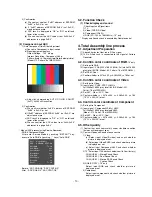
4.6. Power consumption confirmation
(1) Check if Power LED Color and Power Consumption
operate as standard.
(2) Measurement Condition : 230V@ 60Hz (Analog)
(3) Confirm Stand-by operation.
4.7. DDC EDID
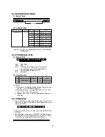
(1) Connect D-sub Signal Cable to D-Sub Connector.
(2) Write EDID data to EEPROM(24C02) by using DDC2B
protocol.
(3) Check whether written EDID data is correct or not. (refer to
Product spec).
4.8. Outgoing condition Configuration
(1) After all function test, press IN-STOP Key by Service
Remote control. And make ship condition.
(2) When pressing IN-STOP key by service remote control,
green and red LED are blinked alternatively. And then
Automatically turn off.(Must not AC power off during
blinking)
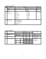
4.9. Option data setting (SVC OSD setting)
- NTSC Service Mode OPTION DATA(According to Suffix)
5. Adjustment Command
5.1. Adjustment Command(LENGTH=84)
15LS1RA-MK
20LS1RA-MK
3970
1920
Resolution
2
0
Module
0
0
TV
1
1
Video
1
1
COMPONENT
1
1
PC-RGB
1
0
DVI
0
0
HDMI
0
0
Area Option[A B]
PAL
(A)
0 : FACTORY MODE OFF
1 : FACTORY MODE ON
[Caution] FACTORY MODE ON only used in factory.
(B) 0: default Option setting.
1~4: The other Area Option setting.(Reserved)
[Caution] Initial Setting of Area Option is [1 0] in production line.
After IN-STOP, Area Option will change [0 0].
If Area Option isn’t 00 after IN-STOP, must change to 00. (Using
G
key on R/C)
NTSC
S. Am : For South America
Korea : For Korea
Item
Condition
Remark
2HR-OFF
1
0 : 2 Hour off option-OFF
1 : 2 Hour off option-ON
FACTORY-MODE
0
0 : EEPROM Write Protection On
1 : EEPROM Write Protection Off
CHANNEL-MUTE
1
0 : Channel Mute Off
1 : Channel Mute On
VAL
00
00
data
00
00 – 100
00 – 100
00 – 100
00 – 100
00 – FF
00 – FF
00 – FF
00 – 7F
00 – 7F
00 – 7F
00 – 3F
00 - 64
02
0, 1, 2, 3
00, FF
0, 1, 2, 3
Description
EEPROM all clear
EEPROM Read
EEPROM Write by
some values
Color Save
They have different
range each mode,
FOS Adjustment
Drive adjustment
Offset adjustment
Bright adjustment
Luminance adjustment
Auto COLOR
Adjustment
0: COOL
1: NORMAL
2: WARM
3: USER
00: Factory mode off
FF: Factory mode On
0 : TV
1 : AV1
2 : AV2
3 : Component
4 : RGB
5 : DVI
No.
1
2
3
4
5
6
7
8
9
10
11
12
13
14
15
16
17
18
19
20
Adjustment Contents
EEPROM ALL INIT.
EEPROM Read
EEPROM Write
COLOR SAVE
(R/G/B cutoff, Drive,
Contrast, Bright)
H POSITION
V POSITION
CLOCK
PHASE
R DRIVE
G DRIVE
B DRIVE
R CUTOFF
G CUTOFF
B CUTOFF
BRIGHT
CONTRAST
AUTO_COLOR_
ADJUST
CHANGE_COLOR_
TEMP
FACTORY_
DEFAULT
AUTO_
INPUTCHANGE
CMD(hex)
E4
E7
E8
EB
20
30
90
92
16
18
1A
80
82
84
10
12
F1
F2
F3
F4
ADR
00
00
00
00
00
00
00
00
00
00
00
00
00
00
00
00
00
00
00
00
Summary of Contents for 15LS1RA
Page 19: ... 19 MEMO ...
Page 20: ... 20 EXPLODED VIEW 300 200 120 120 590 431 580 520 411 400 530 441 440 430 ...
Page 22: ......
Page 23: ......

