background image

14

ENGLISH


Make sure that children do not 
climb on or hang on the TV.


Use a platform or cabinet that is 
strong and large enough to support 
the TV securely.


When installing the product, 
first check that the wall is strong 
enough. Use the anchors and screws 
provided.


-

If you use anchors and screws 
that are not specified by the 
manufacturer, they may not hold 
the weight of the product, causing 
safety issues.


Be sure to use the accessory cable 
provided. Otherwise, friction 
between the product and the wall 
may cause damage to the connector.


When drilling holes into the wall, 
make sure you use a drill and drill 
bit with the specified diameter. 
Ensure that you also follow the 
instructions regarding the depth of 
the holes.


-

Otherwise, the product may be 
installed incorrectly and cause 
safety issues.


Wear safety gloves when installing 
the product. Do not use your bare 
hands.


-

Otherwise, it may cause personal 
injury.


If some parts of the wall mount 
do not touch the wall after it is 
attached, use the double-sided tape 
included in the accessory box to 
stick the mount to the wall.


If some parts of the wall mount do 
not touch the wall after using the 
wall mounting screws for wood, use 
the remaining screws.


Be sure to use only the exclusive 
wall mounting screws provided as 
accessories.


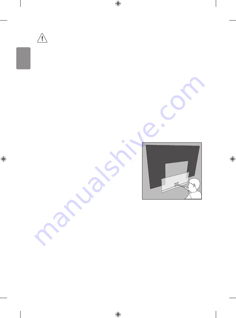
If you want to connect the TV Cable 
is connected to the back panel 
partition, please use the enclosed 
Punching Guide.

Summary of Contents for OLED65W7 Series

Page 1: ...www lg com X 7 M5 X L65 X 7 12 14 16 20 a X 2 M3 X L10 CR2032 AA AA b c d e OLED65W7 f X 5 2 Ø5 X L65 e X 5 2 OLED77W7 f X 8 2 Ø5 X L65 e X 8 2 Depending on model Modele bağlı olarak değişkenlik gösterebilir OLED65W7 https youtu be frR9EA89e4A X 5 4 Ø3 X L18 X 8 4 Ø3 X L18 ...

Page 2: ......

Page 3: ...2 1 3 4 5 ...

Page 4: ...OLED65W7 e f e f 6 6 7 7 OLED77W7 480 mm 400 mm ...

Page 5: ...8 10 9 11 ...

Page 6: ...12 15 13 16 14 17 ...

Page 7: ...18 19 ...

Page 8: ...20 21 ...

Page 9: ...23 1 2 a b 22 ...

Page 10: ...HDMI IN LAN USB IN AUDIO OUT H P OUT ANTENNA CABLE IN HDMI IN ARC ...

Page 11: ...LAN AUDIO OUT H P OUT Satellite IN OPTICAL DIGITAL AUDIO OUT PCMCIA CARD SLOT ...

Page 12: ...COMPONENT IN AV IN VIDEO VIDEO L MONO AUDIO R AUDIO ...

Page 13: ...1 2 a b 3 4 a c 1 2 e d ...

Page 14: ...1 3 2 AA 1 2 4 3 1 2 4 3 ...

Page 15: ...1 2 1 2 3 ...

Page 16: ...A B C D E F G H I OLED65W7V Z 1450 825 3 85 7 6 1260 78 198 10 0 2 3 OLED77W7V Z 1721 989 5 96 12 3 1460 84 208 13 1 5 0 Power requirement Güç gereksinimi AC 100 240 V 50 60 Hz 1 2 0 B E C A F G H D I ...

Page 17: ......

Page 18: ......

Page 19: ......

Page 20: ... MFL69649064 ...

Page 21: ...nual carefully before operating your set and retain it for future reference www lg com P NO MFL69727245 1704 REV00 Printed in Korea Safety and Reference MFL69727245 Copyright ⓒ 2017 LG Electronics Inc All Rights Reserved ...

Page 22: ...uch as stoves and other devices that produce heat Near kitchen counters or humidifiers where they can easily be exposed to steam or oil An area exposed to rain or wind Near containers of water such as vases Otherwise this may result in fire electric shock malfunction or product deformation Do not place the product where it might be exposed to dust This may cause a fire hazard Mains Plug is theTV c...

Page 23: ...a small child does not consume them Please seek Doctor Medical Attention immediately if child consumes batteries Do not insert any metal objects conductors like a metal chopstick cutlery screwdriver into the end of power cable while the power plug is plugged into wall socket Additionally do not touch the power plug right after unplugging from the wall socket You may be electrocuted Do not put or s...

Page 24: ...roved by LG Electronics Otherwise this may result in fire electric shock malfunction or product deformation Never Disassemble the AC adapter or power cord This may result in fire or electric shock Be careful in handling the adapter to prevent any external shocks to it An external shock may cause damage to the adapter Make sure the power cord is connected securely to the power plug on theTV Install...

Page 25: ...for switch It may cause mechanical failure or could give an electric shock Please follow the installation instructions below to prevent the product from overheating The distance between the product and the wall should be more than 10 cm Do not install the product in a place with no ventilation e g on a bookshelf or in a cupboard Do not install the product on a carpet or cushion Make sure the air v...

Page 26: ...been dropped Do not use high voltage electrical goods near theTV e g electric mosquito swatter This may result in product malfunction When cleaning the product and its components unplug the power first and wipe it with a soft cloth Applying excessive force may cause scratches or discolouration Do not spray the panel with water or wipe with a wet cloth Never use glass cleaner car or industrial shin...

Page 27: ... speaker This may result in product damage or degradation Only OLED65 77W7 Do not use any unapproved items to ensure the safety and product life span Any damage or injuries caused by using unapproved items are not covered by the warranty Some models have a thin film attached on to the screen and this must not be removed When attaching the stand to theTV set place the screen facing down on a cushio...

Page 28: ...ge Hold the top and bottom of theTV frame firmly Make sure not to hold the transparent part speaker or speaker grill area When transporting a largeTV there should be at least 2 people When transporting theTV by hand hold the TV as shown in the following illustration When transporting theTV do not expose the TV to jolts or excessive vibration When transporting theTV keep theTV upright never turn th...

Page 29: ... to the AV box first may cause injury to your fingers Only OLED65 77G7 Using the button Depending on model You can simply operate theTV functions using the button A type B type Basic functions Power On Press Power Off Press and hold 1 Volume Control Programmes Control 1 All running apps will close and any recording in progress will stop Adjusting the menu When theTV is turned on press the button o...

Page 30: ...a wall This feature is not available for all models 1 Insert and tighten the eye bolts orTV brackets and bolts on the back of theTV If there are bolts inserted at the eye bolts position remove the bolts first 2 Mount the wall brackets with the bolts to the wall Match the location of the wall bracket and the eye bolts on the rear of theTV 3 Connect the eye bolts and wall brackets tightly with a stu...

Page 31: ...unt bracket please use a wall mount bracket where the device is adequately secured to the wall with enough space to allow connectivity to external devices It is advised to connect all the cables before installing fixed wall mounts Make sure to use screws and wall mount bracket that meet theVESA standard Standard dimensions for the wall mount kits are described in the following table Separate purch...

Page 32: ...nt Punching Guide Wall mounting screw Ø5 x L65 Wall mounting anchor Wall mounting screw for wood Ø3 x L18 Check the material of the wall and the thickness of the finishing Use theWall mount anchor for wall material of concrete light concrete strong natural stone soft natural stone masonry brick and hallow block that do not crack Wall Material Tools Wall Width Concrete Wallmounting anchor Wall moun...

Page 33: ...Ø 8 mm drill bit for concrete and hammer Impact drill Tools you will need Phillips head driver manual or motorized Ø 3 6 8 mm Drill bit Level Stud finder Drill How to attach to masonry walls Please follow the below direction 1 Use a drill bit Ø 8 mm to drill a hole for the anchor location within a depth of 80 mm to 100 mm 2 Clean the drilled hole 3 Insert the sealed wall mounting anchor to the hol...

Page 34: ... and drill bit with the specified diameter Ensure that you also follow the instructions regarding the depth of the holes Otherwise the product may be installed incorrectly and cause safety issues Wear safety gloves when installing the product Do not use your bare hands Otherwise it may cause personal injury If some parts of the wall mount do not touch the wall after it is attached use the double s...

Page 35: ...der of theTV port If you record aTV program on a DVD recorder orVCR make sure to connect theTV signal input cable to theTV through a DVD recorder orVCR For more information of recording refer to the manual provided with the connected device Refer to the external equipment s manual for operating instructions If you connect a gaming device to theTV use the cable supplied with the gaming device In PC...

Page 36: ...s not inserted properly this can cause damage to theTV and the PCMCIA card slot If theTV does not display any video and audio when CI CAM is connected please contact to theTerrestrial Cable Satellite Service Operator USB connection Some USB Hubs may not work If a USB device connected through a USB Hub is not detected connect it directly to the USB port on theTV Other connections Connect yourTV to ...

Page 37: ...toward the remote control sensor on theTV EXIT BACK STB PWR A A POWER Turns theTV on or off You can turn your set top box on or off by adding the set top box to the universal remote control for yourTV Adjusts the volume level Scrolls through the saved programmes MUTE Mutes all sounds Returns to the previous level Clears on screen displays and returns to last input viewing HOME Accesses the Home me...

Page 38: ...teries might have been swallowed or placed inside any part of the body seek immediate medical attention If you have long nails do not open the battery cover by using your finger Or else your nail could break Magic remote functions When the message Magic remote battery is low Change the battery is displayed replace the battery To replace batteries open the battery cover replace batteries 1 5V AA ma...

Page 39: ...creen SEARCH Search for content such as TV programmes movies and other videos or perform a web search by entering text in the search bar GUIDE LIST STB TEXT T OPT FOCUS MENU RECENT EXIT BACK LIVE ZOOM 9wxyz 8tuv 7pqrs 0 B 1 2 1 B HOME Accesses the Home menu Shows the previous history 1 Displays the set top box Home menu When you are not watching via a set top box the display changes to the set top...

Page 40: ...an view it in full screen You can zoom in on the area where the remote control is pointed These access special functions in some menus To use the button press and hold for more than 3 seconds Registering magic remote How to register the magic remote To use the Magic Remote first pair it with your TV 1 Put batteries into the Magic Remote and turn theTV on 2 Point the Magic Remote at yourTV and pres...

Page 41: ... visit www lg com Troubleshooting Cannot control theTV with the remote control Check the remote control sensor on the product and try again Check if there is any obstacle between the product and the remote control Check if the batteries are still working and properly installed to to No image display and no sound is produced Check if the product is turned on Check if the power cord is connected to ...

Page 42: ...here is no need to be concerned Only OLED65 77W7 A blue light blinks on the front of the Companion Box AV Box TheTV may have a problem with the cooling fan or the temperature in theTV may be too high Contact an authorized service center A magenta light blinks on the front of the Companion Box AV Box TheTV may have a problem in the moving speaker Contact an authorized service center An orange light...

Page 43: ...ody Wireless module LGSBWAC72 specifications Wireless LAN IEEE 802 11a b g n ac Frequency range Output power Max 2400 to 2483 5 MHz 5150 to 5725 MHz 5725 to 5850 MHz Not for EU 14 dBm 16 5 dBm 11 5 dBm Bluetooth Frequency range Output power Max 2400 to 2483 5 MHz 8 5 dBm Wireless function S W version 1 0 IEEE 802 11ac is not available in all countries CI Module W x H x D 100 0 mm x 55 0 mm x 5 0 m...

Page 44: ...G D K I SECAM L Channel coverage Band DVB S S2 DVB C DVB T T2 46 862 MHz 950 2150 MHz 46 890 MHz VHF III 174 230 MHz UHF IV 470 606 MHz UHFV 606 862 MHz S Band II 230 300 MHz S Band III 300 470 MHz Maximum number of storable programmes 6 000 2 000 External antenna impedance 75 Ω Wireless function S W version 1 0 ...

Page 45: ......

Page 46: ...MODEL SERIAL Record the model number and serial number of the TV Refer to the label on the back cover and quote this information to your dealer when requiring any service ...

Page 47: ...OWNER S MANUAL EXTERNAL CONTROL DEVICE SETUP www lg com Please read this manual carefully before operating the set and retain it for future reference ...

Page 48: ...R C Button 1A Q View Flashback R C Button 8E Forward R C Button 1E FAV Favorite Channel R C Button 8F Rewind R C Button 20 Text Teletext R C Button AA Info R C Button 21 T Opt Teletext Option R C Button AB Program Guide R C Button 28 Return BACK R C Button B0 Play R C Button 30 AV Audio Video Mode R C Button B1 ꕗ Stop File List R C Button 39 Caption Subtitle R C Button BA ꕘ Freeze Slow Play Pause ...

Page 49: ...CONTROL SERVICE TV TV PC TV PC SERVICE ONLY RS 232C IN CONTROL SERVICE RS 232C IN CONTROL SERVICE 1 3 2 1 3 2 LGTV supports PL2303 chip based Vendor ID 0x0557 Product ID 0x2008 USB to serial converter which is not made nor provided by LG It can be purchased from computer stores that carry accessories for IT support professionals RS 232C With RS232C Cable DE9 D Sub 9pin Type You need to purchase th...

Page 50: ...C TV PC SERVICE ONLY RS 232C IN CONTROL SERVICE RS 232C IN CONTROL SERVICE 1 3 2 1 3 2 Customer Computer RS 232C configurations 3 Wire Configurations Not standard 1 6 5 9 PC TV RXD 2 2 TXD TXD 3 1 RXD GND 5 3 GND OR RXD 3 2 TXD TXD 2 1 RXD GND 5 3 GND D Sub 9 Phone RS 232C Serial port Set ID For Set ID number see Real Data Mapping on p 6 1 Press SETTINGS to access the main menus 2 Press the Naviga...

Page 51: ... to 05 06 Contrast k g 00 to 64 20 Tune Command m a p 9 07 Brightness k h 00 to 64 21 Channel Programme Add Del Skip m b 00 to 01 08 Color Colour k i 00 to 64 22 Key m c Key Codes 09 Tint k j 00 to 64 23 Control Backlight Control Panel Light m g 00 to 64 10 Sharpness k k 00 to 32 24 Input select Main x b p 11 11 OSD Select k l 00 to 01 25 3D Only 3D models x t p 11 12 Remote Control Lock Mode k m ...

Page 52: ... OK Data x The set transmits ACK acknowledgement based on this format when receiving normal data At this time if the data is data read mode it indicates present status data If the data is data write mode it returns the data of the PC computer Error Acknowledgement Command2 Set ID NG Data x The set transmits ACK acknowledgement based on this format when receiving abnormal data from non viable funct...

Page 53: ... may work differently based on model and is supported for DTV fully and ATV AV partially 03 Screen Mute Command k d To select screen mute on off Transmission k d Set ID Data Cr Data 00 Screen mute off Picture on Video mute off 01 Screen mute on Picture off 10 Video mute on Ack d Set ID OK NG Data x In case of video mute on only TV will display On Screen Display OSD But in case of Screen mute on TV...

Page 54: ... not turn on by power on key of IR Local Key 13 Treble Command k r To adjust treble You can also adjust in the AUDIO menu Transmission k r Set ID Data Cr Data Min 00 to Max 64 Ack r Set ID OK NG Data x Depending on model 14 Bass Command k s To adjust Bass You can also adjust in the AUDIO menu Transmission k s Set ID Data Cr Data Min 00 to Max 64 Ack s Set ID OK NG Data x Depending on model 15 Bala...

Page 55: ...Antenna TV 00 Result ma 00 00 0a 00 2 Tune to the digital antenna DVB T Channel 01 Set ID All 00 Data 00 01 Channel Data is 1 00 01 Data 02 Digital Antenna TV 10 Result ma 00 00 01 10 3 Tune to the satellite DVB S Channel 1000 Set ID All 00 Data 00 01 Channel Data is 1000 03 E8 Data 02 Digital Satellite TV 40 Result ma 00 03 E8 40 Ack a Set ID OK Data 00 Data 01 Data 02 x a Set ID NG Data 00 x For...

Page 56: ... Channel Data Data 04 Low byte Channel Data Data 05 Input Source Digital Satellite for Japan 02 Antenna TV DTV 07 BS Broadcasting Satellite 08 CS1 Communication Satellite 1 09 CS2 Communication Satellite 2 Tune Command Examples 1 Tune to the digital antenna ISDB T channel 17 1 Set ID All 00 Data 00 Don t know Physical 00 Data 01 02 Major is 17 00 11 Data 03 04 Minor Branch is 1 00 01 Data 05 Digit...

Page 57: ...ng If Data 00 is 00 3D On or 03 2D to 3D Data 03 works when 3D Mode Genre is manual only All 3D pattern options Data 01 may not be available according to broadcasting video signal Data 00 Data 01 Data 02 Data 03 00 O O O 01 X X X 02 X X X 03 X O O X don t care Ack t Set ID OK Data00 Data01 Data02 Data03 x t Set ID NG Data00 x 26 Extended 3D Command x v only 3D models Depending on model To change 3...

Page 58: ...ICE SETUP 27 Auto Configure Command j u Depending on model To adjust picture position and minimize image shaking automatically It works only in RGB PC mode Transmission j u Set ID Data Cr Data 01 Run Auto Configure Ack u Set ID OK NG Data x ...

Reviews: