background image

TCP/IP C

ONFIGURATION

3-12

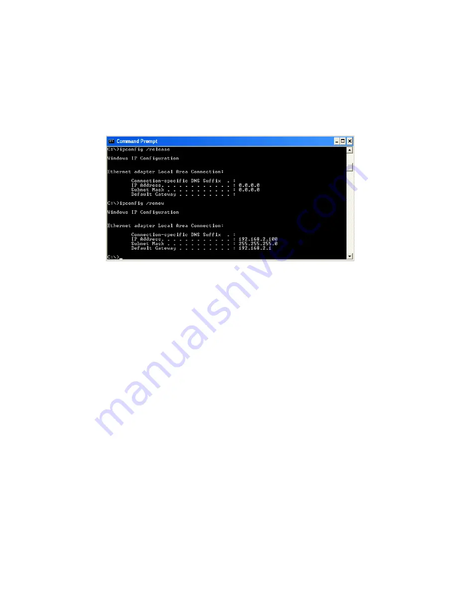
3. Type “IPCONFIG /RENEW” and press the 

Enter

 key. Verify that 

your IP Address is now 

192.168.2.xxx

, your Subnet Mask is 

255.255.255.0

 and your Default Gateway is 

192.168.2.1

. These values 

confirm that your 

LNWR100T

 is functioning correctly.

Type “EXIT” and press the 

Enter

 key to close the Command Prompt 

window.

Your computer is now configured to connect to the 

LNWR100T

.

Summary of Contents for ELO WR100T

Page 1: ...LG Nortel ELO WR100T LNWR100T Wireless Broadband Router User Guide ...

Page 2: ...NSTALLATION OR TESTING UNAUTHORIZED ATTEMPTS TO REPAIR OR ANY OTHER CAUSE BEYOND THE RANGE OF THE INTENDED USE OR BY ACCIDENT FIRE LIGHTNING OR OTHER HAZARD LIMITATION OF LIABILITY IN NO EVENT WHETHER BASED IN CONTRACT OR TORT INCLUDING NEGLIGENCE SHALL LG NORTEL BE LIABLE FOR INCIDENTAL CONSEQUENTIAL INDIRECT SPECIAL OR PUNITIVE DAMAGES OF ANY KIND OR FOR LOSS OF REVENUE LOSS OF BUSINESS OR OTHER...

Page 3: ... or an experienced radio TV technician for help This device complies with Part 15 of the FCC Rules Operation is subject to the following two conditions 1 This device may not cause harmful interference and 2 this device must accept any interference received including interference that may cause undesired operation FCC Caution Any changes or modifications not expressly approved by the party responsi...

Page 4: ...0T to your LAN 2 8 Connect the Power Adapter 2 9 3 Configuring The Client PC 3 1 TCP IP Configuration 3 2 Windows 2000 3 3 Obtain IP Settings From Your LNWR100T 3 5 Manual IP Configuration 3 7 Windows XP 3 9 Disable HTTP Proxy 3 14 Configuring Your Macintosh Computer 3 15 Disable HTTP Proxy 3 17 4 Configuring the LNWR100T 4 1 Navigating the Web Browser Interface 4 2 Making Configuration Changes 4 ...

Page 5: ...P 4 23 Wireless 4 24 Channel and SSID 4 25 WDS 4 26 Security 4 27 Firewall 4 28 Schedule Rule 4 29 Edit Schedule Rule 4 30 Access Control 4 31 Access Control Add PC 4 32 MAC Filter 4 33 Parental Control 4 34 Intrusion Detection 4 35 DMZ 4 41 Wireless 4 42 Wireless Encryption 4 43 Access Control 4 44 WEP 4 45 WPA WPA2 4 47 802 1X 4 49 Advanced Settings 4 51 NAT 4 52 Address Mapping 4 53 Virtual Ser...

Page 6: ... 61 Password Settings 4 62 Remote Management 4 63 SNMP 4 64 Community 4 64 Trap 4 65 UPnP 4 66 Routing 4 67 Static Route 4 67 RIP 4 68 Routing Table 4 70 A Troubleshooting A 1 B Cables B 1 Ethernet Cable B 1 Specifications B 1 Wiring Conventions B 1 RJ 45 Port Ethernet Connection B 2 Pin Assignments B 3 C Specifications C 1 ...

Page 7: ...cal area network LAN to the Internet For those who want to surf the Internet in the most s ecure way this router provides a convenient and powerful solution About the LNWR100T The LNWR100T provides Internet access to multiple users by sharing a single user account This new technology provides many secure and cost effective functions It is simple to configure and can be up and running in minutes ...

Page 8: ...T NAT also enables multi user Internet access via a single user account and virtual server functionality providing protected access to Internet services such as web FTP email and Telnet VPN pass through IPSec ESP Tunnel mode L2TP PPTP User definable application sensing tunnel supports applications requiring multiple connections Easy setup through a web browser on any operating system that supports...

Page 9: ... your computer Shared IP Address The LNWR100T provides Internet access for up to 253 users via a single shared IP address Using only one ISP account multiple users on your network can browse the web at the same time Virtual Server If you have a fixed IP address you can set the LNWR100T to act as a virtual host for network address translation Remote users access various services at your site using ...

Page 10: ...an and TCP SYN flooding WPA WPA2 WEP SSID and MAC filtering provide security over the wireless network Virtual Private Network VPN Pass through The LNWR100T supports three of the most commonly used VPN protocols PPTP L2TP and IPSec The VPN protocols supported by the LNWR100T are briefly described below Point to Point Tunneling Protocol Provides a secure tunnel for remote client access to a PPTP se...

Page 11: ...guring the LNWR100T on page 4 1 Package Contents After unpacking the LNWR100T check the contents of the box to be sure you have received the following components LNWR100T 802 11g Turbo 108Mbps Wireless Broadband Router Power adapter One CAT 5 Ethernet cable RJ 45 One documentation CD Quick Installation Guide Immediately inform your distributor or reseller in the event of any incorrect missing or d...

Page 12: ...can be connected directly to your PC or to a local area network using the Fast Ethernet LAN port Access speed to the Internet depends on your service type Full rate ADSL provides up to 8 Mbps downstream and 1 Mbps upstream G lite or splitterless ADSL provides up to 1 5 Mbps downstream and 512 kbps upstream However you should note that the actual rate provided by specific service providers may vary...

Page 13: ...ble LED Status Description LAN 1 4 On Ethernet link Flashing The LAN port is sending or receiving data Off No Ethernet link WLAN On WLAN link Flashing The LNWR100T is sending or receiving data via WLAN Off No WLAN link PPPoE DSL On PPPoE DSL connection is functioning correctly Flashing The LNWR100T is establishing an PPPoE DSL link Off PPPoE DSL connection is not established WAN On WAN link Off No...

Page 14: ...port RJ 45 Connect your WAN line to this port LAN Ports Fast Ethernet ports RJ 45 Connect devices on your local area network to these ports i e a PC hub switch or IP set top box Reset Button Use this button to reset the power and restore the default factory settings To reset without losing configuration settings see Reset on page 4 60 Antenna Connector Antenna is connected here 12V 1A WAN LAN1 LAN...

Page 15: ...eeded You should however comply with the following guidelines Keep the LNWR100T away from any heating devices Do not place the LNWR100T in a dusty or wet environment You should also remember to turn off the power remove the power cord from the outlet and keep your hands dry when you install the LNWR100T Connect the ADSL Cable Modem Line Connectthe ADSL cablemodemusingaCAT 5Ethernetcable RJ 45 to t...

Page 16: ...ice provider will attach the outside ADSL line to a data voice splitter Use a straight through CAT 5 Ethernet cable RJ 45 to connect the LNWR100T to the cable DSL modem Figure 2 3 Installing with a Splitter Voice Data Residential Connection Point NID Plain Old Telephone System POTS or Ethernet hub or switch LNWR100T Splitter Modem ...

Page 17: ...phone system Use a straight through CAT 5 Ethernet cable RJ 45 to connect the LNWR100T to the cable DSL modem You will have to add low pass filters to your phones as shown below Figure 2 4 Installing without a Splitter Plain Old Telephone System POTS Filter or Ethernet hub or switch Voice Data Voice Data Data Voice Residential Connection Point Network Interface Device NID LNWR100T Modem ...

Page 18: ...her network equipment to the hub or switch When inserting an RJ 45 connector be sure the tab on the connector clicks into position to ensure that it is properly seated Warning Do not plug a phone jack connector into an RJ 45 port This may damage the LNWR100T Instead use only twisted pair cables with RJ 45 connectors that conform with FCC standards Notes 1 Use 100 ohm shielded or unshielded twisted...

Page 19: ...er indicator on the front panel is lit If the power indicator is not lit refer to Troubleshooting on page A 1 In case of a power input failure the LNWR100T will automatically restart and begin to operate once the input power is restored If the LNWR100T is properly configured it will take about 30 seconds to establish a connection with the ADSL service provider after powering up ...

Page 20: ...o configure your computer to connect to the LNWR100T You can either configure your computer to automatically obtain IP settings DHCP or manually configure IP address settings Static IP Depending on your operating system see Windows 2000 on page 3 3 Windows XP on page 3 9 or Configuring Your Macintosh Computer on page 3 15 ...

Page 21: ...00T The default network settings for the LNWR100T are IP Address 192 168 2 1 Subnet Mask 255 255 255 0 Note These settings can be changed to fit your network requirements but you must first configure at least one computer to access the LNWR100T s web configuration interface in order to make the required changes See Configuring the LNWR100T on page 4 1 for instructions on configuring the LNWR100T ...

Page 22: ... Windows 2000 DHCP IP Configuration 1 On the Windows desktop click Start Settings Network and Dial Up Connections 2 Click the icon that corresponds to the connection to your 3 The connection status screen will open Click Properties ...

Page 23: ...uble click Internet Protocol TCP IP 5 If Obtain an IP address automatically and Obtain DNS server address automatically are already selected your computer is already configured for DHCP If not select these options now and click OK ...

Page 24: ... it needs to obtain new network settings By releasing old DHCP IP settings and renewing them with settings from your LNWR100T you can verify that you have configured your computer correctly 1 On the Windows desktop click Start Programs Accessories Command Prompt 2 In the Command Prompt window type IPCONFIG RELEASE and press the Enter key ...

Page 25: ...er key Verify that your IP Address is now 192 168 2 xxx your Subnet Mask is 255 255 255 0 and your Default Gateway is 192 168 2 1 These values confirm that your LNWR100T is functioning correctly 4 Type EXIT and press the Enter key to close the Command Prompt window ...

Page 26: ...DNS server addresses 4 Enter the IP address for the LNWR100T in the Preferred DNS server field This automatically relays DNS requests to the DNS server s provided by your ISP Otherwise add a specific DNS server into the Alternate DNS Server field and click OK to close the dialog boxes 5 Record the configured information in the following table TCP IP Configuration Setting IP Address ____ ____ ____ ...

Page 27: ...er click Tools Click Internet Options and then the Connections tab shown on the right In the Local Area Network LAN settings section click LAN Settings to display the Local Area Network LAN Settings pop up window below In the Proxy server section ensure the Use a proxy server for your LAN These settings will not apply to dial up or VPN connections check box is not ticked Click OK Your computer is ...

Page 28: ...Start Control Panel 2 In the Control Panel window click Network and Internet Connections 3 The Network Connections window will open Locate and double click the Local Area Connection icon for the Ethernet adapter that is connected to the LNWR100T 4 In the connection status screen click Properties ...

Page 29: ...ouble click Internet Protocol TCP IP 6 If Obtain an IP address automatically and Obtain DNS server address automatically are already selected your computer is already configured for DHCP If not select these options now and click OK ...

Page 30: ...T it needs to obtain new network settings By releasing old DHCP IP settings and renewing them with settings from your LNWR100T you can verify that you have configured your computer correctly 1 On the Windows desktop click Start Programs Accessories Command Prompt 2 In the Command Prompt window type IPCONFIG RELEASE and press the Enter key ...

Page 31: ...ddress is now 192 168 2 xxx your Subnet Mask is 255 255 255 0 and your Default Gateway is 192 168 2 1 These values confirm that your LNWR100T is functioning correctly Type EXIT and press the Enter key to close the Command Prompt window Your computer is now configured to connect to the LNWR100T ...

Page 32: ...g DNS server addresses 5 Enter the IP address for the LNWR100T in the Preferred DNS server field This automatically relays DNS requests to the DNS server s provided by your ISP Otherwise add a specific DNS server into the Alternate DNS Server field and click OK to close the dialog boxes 6 Record the configured information in the following table TCP IP Configuration Setting IP Address ____ ____ ___...

Page 33: ...rer click Tools Click Internet Options and then the Connections tab shown on the right In the Local Area Network LAN settings section click LAN Settings to display the Local Area Network LAN Settings pop up window below In the Proxy server section ensure the Use a proxy server for your LAN These settings will not apply to dial up or VPN connections check box is not ticked Click OK Your computer is...

Page 34: ...y match your operating system This is because these steps and screen shots were created using Mac OS 10 2 Mac OS 7 x and above are similar but may not be identical to Mac OS 10 2 Follow these instructions 1 Pull down the Apple Menu Click System Preferences 2 Double click the Network icon in the Systems Preferences window ...

Page 35: ...or DHCP If not select this option 4 Your new settings are shown in the TCP IP tab Verify that your IP Address is now 192 168 2 xxx your Subnet Mask is 255 255 255 0 and your Default Gateway is 192 168 2 1 These values confirm that your LNWR100T is functioning 5 Close the Network window Now your computer is configured to connect to the LNWR100T ...

Page 36: ...his is so that your browser can view the LNWR100T s HTML configuration pages The following steps are for Internet Explorer Internet Explorer 1 Open Internet Explorer and click the Stop button Click Explorer Preferences 2 In the Internet Explorer Preferences window under Network select Proxies 3 Uncheck all check boxes and click OK ...

Page 37: ...y any Java supported browser such as Internet Explorer 5 5 or above Using the web management interface you can configure the LNWR100T and view statistics to monitor network activity To access the LNWR100T s management interface enter the IP address of the LNWR100T in your web browser http 192 168 2 1 The LNWR100T automatically switches to Port 80 for management access ...

Page 38: ...r Internet connection and basic LAN settings Go to Setup Wizard on page 4 5 Home Network Settings Use the Home Network Settings section to configure your LAN WAN and wireless settings Go to Home Network Settings on page 4 13 Security In this section you can easily configure your wireless security settings Go to Security on page 4 27 Advanced Settings Advanced Settings supports more advanced functi...

Page 39: ... to click the Apply or Save Settings or NEXT button at the bottom of the page to enable the new setting Note To ensure proper screen refresh after a command entry be sure that Internet Explorer 5 5 is configured as follows Under the menu Tools Internet Options General Temporary Internet Files Settings the setting for Check for newer versions of stored pages should be Every visit to the page ...

Page 40: ...CONFIGURING THE LNWR100T Login Screen The Login screen automatically appears first Enter the default password lgnortel and then click LOGIN 4 4 ...

Page 41: ...up Wizard Getting Started The Setup Wizard automatically appears next The first item in the Setup Wizard is Getting Started Simply click NEXT to proceed to the following screen and configure your Wireless Settings 4 5 ...

Page 42: ... same on the LNWR100T and all of its wireless clients Broadcast Wireless Network Enable or disable the broadcasting of the SSID If Name you disable broadcast of the SSID only devices that have the correct SSID can connect This nullifies the wireless network discovery feature of some products such as Windows XP Default Enable Wireless Mode This device supports the following modes 11g only 11b only ...

Page 43: ...oughput via time period overhead reduction Standards based 802 11e subset Relevant to STA Advantage applies to any AP Compression Real time hardware data Increased data throughput Standards based Lempel Ziv using compressed frames No impact on host processor Fast Frames Utilizes frame aggregation Increases throughput by and timing modifications transmitting more data per frame Dynamic Turbo Simila...

Page 44: ...rnet Settings Specify the WAN connection type required by your Internet Service Provider Specify Cable modem Fixed IP xDSL PPPoE xDSL or PPTP Select your connection type to proceed Click BACK to go back and change your settings 4 8 ...

Page 45: ...ZARD Cable Modem Settings If the ISP requires you to input a Host Name type it in the Host Name field The MAC Address field will be filled automatically Click NEXT to proceed or BACK to change your settings 4 9 ...

Page 46: ...100T ADSL Settings Fixed IP xDSL Enter the IP address Gateway IP address DNS IP address and Subnet Mask provided to you by your ISP in the appropriate fields below Click NEXT to proceed or BACK to change your settings 4 10 ...

Page 47: ...reason to change it Enter the maximum idle time for the Internet connection After this time has been exceeded the connection will be terminated Check the Auto reconnect check box to automatically reestablish the connection as soon as you attempt to access the Internet again Click NEXT to proceed or BACK to change your settings Note Clicking NEXT will not automatically connect the LNWR100T to the I...

Page 48: ......

Page 49: ...RK SETTINGS Home Network Settings Clicking the Home icon at any time returns you to this home page The Main Menu links are used to navigate to other menus that display configuration parameters and statistics 4 13 ...

Page 50: ...ptions General Temporary Internet Files Settings the setting for Check for newer versions of stored pages should be Every visit to the page Menu Description Status Provides WAN connection type and status firmware and hardware version numbers system IP settings as well as DHCP NAT and firewall information Displays the number of attached clients the firmware versions the physical MAC address for eac...

Page 51: ...ATION CHANGES Status The Status screen displays WAN LAN connection status firmware and hardware version numbers as well as information on DHCP clients connected to your network You can also view the Security Log 4 15 ...

Page 52: ......

Page 53: ... Settings parameters are listed below Parameter Description Wireless Router IP Address IP Address The IP address of the LNWR100T IP Subnet Mask The IP subnet mask DHCP Server DHCP Server DHCP allows individual computers to obtain the TCP IP configuration at startup from a centralized DHCP server To dynamically assign an IP address to a client PC enable the DHCP Dynamic Host Configuration Protocol ...

Page 54: ...IP address pool Domain Name The domain name is the name you assign to your network Lease Time The length of time the DHCP server will reserve the IP address for each computer Setting lease times for shorter intervals such as one day or one hour frees IP addresses after the specified period of time This also means that a particular computer s IP address may change over time If you have set any adva...

Page 55: ...ION CHANGES WAN Settings Specify the WAN connection type required by your Internet Service Provider Specify Dynamic IP Address PPPoE PPTP or Static IP Address Select the connection type and click More Configuration 4 19 ...

Page 56: ...e the Clone MAC Address button to copy the MAC address of the Network Interface Card NIC installed in your PC to replace the WAN MAC address If necessary you can use the Renew button on the Status page to renew the WAN IP address Note Make sure you record the MAC address that you clone so that if you lose your settings you will be able to re connect to the Internet Click Save Settings to proceed o...

Page 57: ...ime in minutes to define a maximum period of time for which the Internet connection is maintained during inactivity If the connection is inactive for longer than the Maximum Idle Time then it will be dropped You can enable the Auto reconnect option to automatically re establish the connection as soon as you attempt to access the Internet again Click Save Settings to proceed or Cancel to change you...

Page 58: ...ntained during inactivity The default setting is 10 minutes If your ISP charges you by the minute you should change the Idle Time Out to one minute After the Idle Time Out has expired set the action you wish the LNWR100T to take You can tell the device to connect manually or automatically as soon as you try to access the Internet again or to keep the session alive Click Save Settings to proceed or...

Page 59: ...HANGES Static IP If your Service Provider has assigned a fixed IP address enter the assigned IP address subnet mask and the gateway address on this screen Click Save Settings to proceed or Cancel to change your settings 4 23 ...

Page 60: ...d channel number It supports data encryption and client filtering To use the wireless feature check the Enable check box and click Save Settings After clicking Save Settings you will be brought directly to the wireless settings screen in the Security section See Wireless on page 4 24 for details on how to configure wireless security 4 24 ...

Page 61: ...the same on the LNWR100T and all of its wireless clients Broadcast Wireless Network Enable or disable the broadcasting of the SSID If Name you disable broadcast of the SSID only devices that have the correct SSID can connect This nullifies the wireless network discovery feature of some products such as Windows XP Default Enable Wireless Mode This device supports the following modes 11g only 11b on...

Page 62: ...R100T and all of its wireless clients Channel This device supports the following modes 11g only 11b only 11b g mixed mode Super G Dynamic Turbo and Super G Static Turbo MAC Address The media access control address MAC address is a unique identifier attached to each wireless base station Security Displays the security mechanism in use Enable WDS Enables the WDS feature When enabled up to 4 WDS link...

Page 63: ... of Service DoS attacks when activated Its purpose is to allow a private local area network LAN to be securely connected to the Internet The second menu item is Wireless This section allows you to configure wireless security settings according to your environment and the privacy level required To configure your firewall settings click Firewall in the left hand menu 4 27 ...

Page 64: ...ed at devices and networks with a connection to the Internet Their goal is not to steal information but to disable a device or network so users no longer have access to network resources The LNWR100T protects against the following DoS attacks IP Spoofing Land Attack Ping of Death IP with zero length Smurf Attack UDP port loopback Snork Attack TCP null scan and TCP SYN flooding See page 4 46 for de...

Page 65: ...led time Define the schedule on the Schedule Rule page and apply the rule on the Access Control page You may filter Internet access for local clients based on rules Each access control rule may be activated at a scheduled time First define the schedule on the Schedule Rule page then apply the rule on the Access Control page 1 To add a new rule click Add Schedule Rule Proceed to the following page ...

Page 66: ...n the following screen 3 Upon completion click OK to save your schedule rules and then click Save Settings to make your settings to take effect Each access control rule may be activated at a scheduled time First define the schedule on the Schedule Rule page then apply the rule on the Access Control page 4 30 ...

Page 67: ...LNWR100T to enter up to 32 MAC addresses that are not allowed access to the WAN port 1 Click Add PC on the Access Control screen 2 Define the appropriate settings for client PC services as shown on the following screen 3 Click OK and then click Apply to save your settings The following items are displayed on the Access Control screen Parameter Description Enable Filtering Function Enables or disab...

Page 68: ... Always Blocking or to whatever schedule you have defined in the Schedule Rule screen Click OK to save your settings The added PC will now appear in the Access Control page For the URL keyword blocking function you will need to configure the URL address or blocked keyword on the Parental Control page first Click Parental Control to add to the list of disallowed URL s and keywords To enable schedul...

Page 69: ...the access of hosts within the local area network LAN The MAC Filtering Table allows the LNWR100T to enter up to 32 MAC addresses that are allowed access to the WAN port All other devices will be denied access By default this feature is disabled Click Save Settings to proceed or Cancel to change your settings 4 33 ...

Page 70: ...e web sites www somesite com and or keywords you want to block on your network To complete this configuration you will need to create or modify an access rule in Access Control Add PC on page 4 32 To modify an existing rule click the Edit option next to the rule you want to modify To create a new rule click on the Add PC option From the Access Control Add PC section check the option for WWW with P...

Page 71: ...inspects packets at the application layer maintains TCP and UDP session information including timeouts and number of active sessions and provides the ability to detect and prevent certain types of network attacks such as Denial of Service DoS attacks 4 35 ...

Page 72: ... users no longer have access to network resources The LNWR100T protects against DoS attacks including Ping of Death Ping flood attack SYN flood attack IP fragment attack Teardrop Attack Brute force attack Land Attack IP Spoofing attack IP with zero length TCP null scan Port Scan Attack UDP port loopback Snork Attack Note The firewall does not significantly affect system performance so we advise en...

Page 73: ...SPI feature is turned on all incoming packets are blocked except those types marked with a check in the SPI section at the top of the screen RIP Defect Disabled If the router does not reply to an IPX RIP request packet it will stay in the input queue and not be released Accumulated packets could cause the input queue to fill causing severe problems for all protocols Enabling this feature prevents ...

Page 74: ... are taking place only with sources that are known and trusted from previous interactions In addition to being more rigorous in their inspection of packets stateful inspection firewalls also close off ports until a connection to the specific port is requested When particular types of traffic are checked only the particular type of traffic initiated from the internal LAN will be allowed For example...

Page 75: ...o activity UDP session idle timeout 30 secs The length of time for which a UDP session will be managed if there is no activity DoS Detect Criteria Total incomplete TCP UDP sessions HIGH 300 sessions Defines the rate of new unestablished sessions that will cause the software to start deleting half open sessions Total incomplete TCP UDP sessions LOW 250 sessions Defines the rate of new unestablished...

Page 76: ...lete TCP UDP session is detected as incomplete Maximum half open fragmentation packet number from same host 30 sessions Maximum number of half open fragmentation packets from the same host Half open fragmentation detect sensitive time period 1 sec Length of time before a half open fragmentation session is detected as half open Flooding cracker block time 300 secs Length of time from detecting a fl...

Page 77: ...m behind the firewall you can open the client up to unrestricted two way Internet access Enter the IP address of a DMZ Demilitarized Zone host on this screen Adding a client to the DMZ may expose your local network to a variety of security risks so only use this option as a last resort 4 41 ...

Page 78: ...ng clients by setting the Service Set Identifier SSID and channel number It supports data encryption and client filtering To use the wireless feature check the Enable check box and click Save Settings To begin configuring your wireless security settings click Wireless Encryption 4 42 ...

Page 79: ...ables all wireless security To make it easier to set up your wireless network we recommend enabling this setting initially By default wireless security is disabled WEP Only Once you have your wireless network in place the minimum security we recommend is to enable the legacy security standard Wired Equivalent Privacy WEP See WEP on page 4 45 WPA WPA2 Only For maximum wireless security you should e...

Page 80: ...k you can specify that only certain wireless clients can connect to the LNWR100T Up to 32 MAC addresses can be added to the MAC Filtering Table When enabled all registered MAC addresses are controlled by the Access Rule By default this MAC filtering feature is disabled 4 44 ...

Page 81: ...t key to use for encryption Key Entry Method Select hexadecimal Hex or ASCII for the key entry method Key Provisioning Select Static if there is only one fixed key for encryption If you want to select Dynamic you need to enable 802 1X function first Default Key ID Choose which key to use as default Passphrase Check the Passphrase check box to generate a key automatically Key 1 4 The LNWR100T suppo...

Page 82: ...rase can consist of up to 63 alphanumeric characters Hexadecimal Keys A hexadecimal key is a mixture of numbers and letters from A F and 0 9 64 bit keys are 10 digits long and can be divided into five two digit numbers 128 bit keys are 26 digits long and can be divided into 13 twodigit numbers ASCII Keys There are 95 printable ASCII characters 0123456789 ABCDEFGHIJKLMNOPQRSTUVWXYZ _ abcdefghijklmn...

Page 83: ... from Microsoft is available for free download for XP only Parameter Description Cipher Suite The security mechanism used in WPA for encryption Select TKIP AES WPA WPA2 or AES WPA2 Only Authentication Select 802 1X or Pre shared Key for the authentication method 802 1X for the enterprise network with a RADIUS server Pre shared key for the SOHO network environment without an authentication server P...

Page 84: ...otocol EAP authentication or pre shared key PSK technology The passphrase can consist of up to 32 alphanumeric characters WPA2 Launched in September 2004 by the Wi Fi Alliance WPA2 is the certified interoperable version of the full IEEE 802 11i specification which was ratified in June 2004 Like WPA WPA2 supports IEEE 802 1X EAP authentication or PSK technology It also includes a new advanced encry...

Page 85: ... function Session Idle Timeout This is the time in seconds that a session will sit inactive before terminating Set to 0 if you do not want the session to timeout Default 300 seconds Re Authentication The interval time in seconds after which the client Period will be asked to re authenticate For example if you set this to 30 seconds the client will have to re authenticate every 30 seconds Set to 0 ...

Page 86: ... the Network Access Server 802 1X The use of IEEE 802 1X offers an effective framework for authenticating and controlling user traffic to a protected network as well as dynamically varying encryption keys 802 1X ties EAP Extensible Authentication Protocol to both the wired and wireless LAN media and supports multiple authentication methods such as token cards Kerberos one time passwords certificat...

Page 87: ...ription NAT Shares a single ISP account with multiple users sets up virtual servers Maintenance Allows you to backup restore reset and upgrade the LNWR100T s firmware System Sets the local time zone the password for administrator access the IP address of a PC that will be allowed to manage the LNWR100T remotely and the IP address of a Domain Name Server SNMP Community string and trap server settin...

Page 88: ...process allows all of the computers on your home network to use one IP address Using the NAT capability of the LNWR100T you can access the Internet from any computer on your home network without having to purchase more IP addresses from your ISP To use the NAT feature check the Enable check box and click Save Settings 4 52 ...

Page 89: ...e or more addresses used in the public global Internet This feature limits the number of public IP addresses required from the ISP and also maintains the privacy and security of the local network We allow one public IP address to be mapped to a pool of local addresses Click Save Settings to proceed or Cancel to change your settings 4 53 ...

Page 90: ...n the requested service TCP UDP port number the LNWR100T redirects the external service request to the appropriate server located at another internal IP address For example if you set Type Public Port to TCP 80 HTTP or web and the Private IP Port to 192 168 2 2 80 then all HTTP requests from outside users will be transferred to 192 168 2 2 on port 80 Therefore by just entering the IP address provi...

Page 91: ...multiple connections use the following screen to specify the additional public ports to be opened for each application Click the List of well known special applications link for more information Specify the public port number normally associated with an application in the Trigger Port field Set the protocol type to TCP or UDP then enter the ports that the application requires The ports may be in t...

Page 92: ...ications field From the drop down list choose the application and then choose a row number to copy this data into Note Choosing a row that already contains data will overwrite the current settings For a full list of ports and the services that run on them see www iana org assignments port numbers 4 56 ...

Page 93: ...button is provided to refresh the NAT Mapping Table with the most updated values The content of the NAT Mapping Table is described as follows Protocol protocol of the flow Local IP local LAN host s IP address for the flow Local Port local LAN host s port number for the flow Pseudo IP translated IP address for the flow Pseudo Port translated port number for the flow Peer IP remote WAN host s IP add...

Page 94: ...ss Router Configuration and click NEXT to save your LNWR100T s configuration to a file named config bin on your PC You can then check the Restore from saved Configuration file LNWR100T_backup bin radio button and click NEXT to restore the saved backup configuration file To restore the factory settings check Restore Wireless Router toFactory Defaults and click NEXT You will be asked to confirm your...

Page 95: ...rmware to the latest version Click Browse to locate the saved file After locating the new firmware file click BEGIN UPGRADE Follow the instructions to complete the upgrade After restarting check the Status page to make sure the device is running the new code 4 59 ...

Page 96: ...igurations that you have set previously will not be changed back to the factory default settings Note You may also use the blue Reset button on the rear panel of the LNWR100T to perform a reset Push for one second to perform a reboot All of your settings will remain upon restarting Push for six seconds to return the LNWR100T to factory default settings 4 60 ...

Page 97: ...and time server for the LNWR100T This information is used for log entries and client access control Check Enable Automatic Time Server Maintenance to automatically maintain the LNWR100T s system time by synchronizing with a public time server over the Internet Then configure two different time servers by selecting the options in the Primary Server and Secondary Server fields 4 61 ...

Page 98: ...rface press the Reset button colored blue on the rear panel holding it down for at least six seconds to restore the factory defaults The default password is lgnortel Enter a maximum Idle Time Out in minutes to define a maximum period of time an inactive login session will be maintained If the connection is inactive for longer than the maximum idle time it will be logged out and you will have to lo...

Page 99: ...ter on this screen Check the Enabled check box and enter the IP address of the remote host and click Save Settings Note If you check Enabled and specify an IP address of 0 0 0 0 any host can manage the LNWR100T For remote management via WAN IP address you need to connect using port 8080 Simply enter WAN IP address followed by 8080 in the address field of your web browser for example 212 120 68 20 ...

Page 100: ...anagement Station NMS can be used to access this information Access rights to the agent are controlled by community strings To communicate with the LNWR100T the NMS must first submit a valid community string for authentication Parameter Description Community A community name authorized for management access Access Management access is restricted to Read Only Read or Read Write Write Valid Enables ...

Page 101: ...prevent unauthorized individuals from reading information on your system Version Sets the trap status to disabled or enabled with v1 or v2c The v2c protocol was proposed in late 1995 and includes enhancements to v1 that are universally accepted These include a get bulk command to reduce network management traffic when retrieving a sequence of MIB variables and a more elaborate set of error codes f...

Page 102: ...eless devices UPnP architecture leverages TCP IP and the web to enable seamless proximity networking in addition to control and data transfer among networked devices in the home office and everywhere in between Click Enable to turn on the Universal Plug and Play function of the LNWR100T This function allows the device to automatically and dynamically join a network Click Save Settings to proceed o...

Page 103: ...Parameter Description Index Index number of the route Network Address Enter the IP address of the remote computer for which to set a static route Subnet Mask Enter the subnet mask of the remote network for which to set a static route Gateway Enter the WAN IP address of the gateway to the remote network Configure Allows you to edit existing routes Click Save Settings to save the configuration 4 67 ...

Page 104: ...etworks connected to the router If enabled this sub network information will be summarized to one piece of information covering all subnetworks Table of current Interface RIP parameter Interface The WAN interface to be configured Operation Mode Disable RIP disabled on this interface Enable RIP enabled on this interface Silent Listens for route broadcasts and updates its route table It does not par...

Page 105: ...little security as it is possible to learn the authentication key by watching RIP packets Authentication Password Authentication key Code When a router receives a routing update that includes changes to an entry it updates its routing table to reflect the new route RIP routers maintain only the best route to a destination After updating its routing table the router immediately begins transmitting ...

Page 106: ...plate that identifies the address bits in the destination address used for routing to specific subnets Each bit that corresponds to a 1 is part of the subnet mask number each bit that corresponds to 0 is part of the host number Gateway The IP address of the router at the next hop to which frames are forwarded Interface The local interface through which the next hop of this route is reached Metric ...

Page 107: ...ween the LNWR100T the external power supply and the wall outlet If the power indicator does not turn on when the power cord is plugged in you may have a problem with the power outlet power cord or external power supply However if the unit powers off after running for a while check for loose power connections power losses or surges at the power outlet If you still cannot isolate the problem then th...

Page 108: ...lace any defective adapter or cable if necessary Network Connection Problems Cannot ping the LNWR100T from the attached LAN or the LNWR100T cannotping any device on the attached LAN Verify that the IP addresses are properly configured For most applications you should use the router s DHCP function to dynamically assign IP addresses to hosts on the attached LAN However if you manually configure IP ...

Page 109: ...way Check that you have a valid network connection to the router and that the port you are using has not been disabled Check the network cabling between the management station and the router Forgot or lost the password Press the Reset button on the rear panel holding it down for at least six seconds to restore the factory defaults Troubleshooting Chart Symptom Action ...

Page 110: ...the angle of the antenna There may be interference possibly caused by microwave ovens or wireless phones Change the location of the possible sources of interference or change the location of the router Change the wireless channel on the router See Channel and SSID on page 25 Check that the antenna connectors and cabling are firmly connected The LNWR100T cannot be detected by a wireless client The ...

Page 111: ...ntions For Ethernet connections a twisted pair cable must have two pairs of wires Each wire pair is identified by two different colors For example one wire might be red and the other red with white stripes Also an RJ 45 connector must be attached to both ends of the cable Cable Types and Specifications Cable Type Max Length Connector 10BASE T Cat 3 4 5 100 ohm UTP 100 m 328 ft RJ 45 100BASE TX Cat...

Page 112: ...entation when attaching the wires to the pins Figure B 1 RJ 45 Ethernet Connector Pin Numbers RJ 45 Port Ethernet Connection Use the straight through CAT 5 Ethernet cable provided in the package to connect the LNWR100T to your PC When connecting to other network devices such as an Ethernet switch use the cable type shown in the following table Attached Device Port Type Connecting Cable Type MDI X ...

Page 113: ...a Straight Through Wiring If the port on the attached device has internal crossover wiring MDI X then use straight through cable RJ 45 Pin Assignments Pin Number Assignment 1 Tx 2 Tx 3 Rx 6 Rx The and signs represent the polarity of the wires that make up each wire pair Straight Through Cable Pin Assignments End 1 End 2 1 Tx 1 Tx 2 Tx 2 Tx 3 Rx 3 Rx 6 Rx 6 Rx ...

Page 114: ...CABLES B 4 Crossover Wiring If the port on the attached device has straight through wiring MDI use crossover cable Crossover Cable Pin Assignments End 1 End 2 1 Tx 3 Rx 2 Tx 6 Rx 3 Rx 1 Tx 6 Rx 2 Tx ...

Page 115: ... BASE TX ports Auto negotiates the connection speed to 10 Mbps Ethernet or 100 Mbps Fast Ethernet and the transmission mode to half duplex or full duplex WAN Interface 1 ADSL RJ 45 port Indicator Panel LAN 1 4 WLAN PPPoE DSL WAN Power Dimensions 145 x 95 x 36 mm 5 70 x 3 74 x 1 41 in Weight 0 175 kg 0 469 lbs Input Power 9V 1 A Power Consumption 9 Watts maximum ...

Page 116: ...83 TFTP RFC 1483 AAL5 Encapsulation RFC 1661 PPP RFC 1866 HTML RFC 2068 HTTP RFC 2364 PPP over ATM Radio Features Wireless RF module Frequency Band 802 11g Radio 2 4GHz 802 11b Radio 2 4GHz USA FCC 2412 2462MHz Ch1 Ch11 Canada IC 2412 2462MHz Ch1 Ch11 Europe ETSI 2412 2472MHz Ch1 Ch13 Japan STD T66 STD 33 2412 2484MHz Ch1 Ch14 Modulation Type OFDM CCK Operating Channels IEEE 802 11b compliant 11 c...

Page 117: ...15 802 11g 18Mbps 15 802 11g 24Mbps 15 802 11g 36Mbps 15 802 11g 48Mbps 15 802 11g 54Mbps 15 Sensitivity Modulation Rate Receiver 2 412 2 484 HGz Sensitivity dBm 802 11b 1Mbps 90 802 11b 2Mbps 88 802 11b 5 5Mbps 85 802 11b 11Mbps 84 Modulation Rate Receiver Sensitivity Typical dBm 802 11g 6Mbps 88 802 11g 9Mbps 87 802 11g 12Mbps 84 802 11g 18Mbps 82 802 11g 24Mbps 79 802 11g 36Mbps 75 802 11g 48Mb...

Page 118: ...Temperature Operating 0 to 40 C 32 to 104 F Storage 40 to 70 C 40 to 158 F Humidity 5 to 95 non condensing Vibration IEC 68 2 36 IEC 68 2 6 Shock IEC 68 2 29 Drop IEC 68 2 32 IEEE Standards IEEE 802 3 802 3u 802 11g 802 1D ITU G dmt ITU G Handshake ITU T 413 issue 2 ADSL full rate ...

Page 119: ...JAN 2008 ISSUE 1 0 ...

Reviews: