


C
ONFIGURING THE LNWR100T
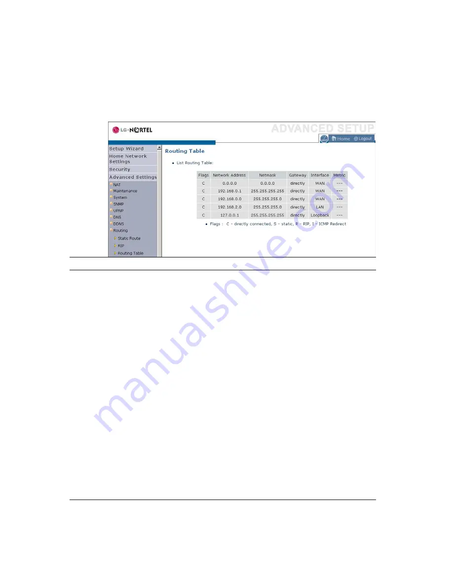
Routing Table
Click
Routing Table
to view the screen below.
Parameter
Description
Flags
Indicates the route status:
C = Direct connection on the same subnet.
S = Static route.
R = RIP (Routing Information Protocol) assigned
route.
I = ICMP (Internet Control Message Protocol)
Redirect route.
Network Address
Destination IP address.
Netmask
The subnetwork associated with the destination.
This is a template that identifies the address bits in
the destination address used for routing to specific
subnets. Each bit that corresponds to a “1” is part of
the subnet mask number; each bit that corresponds to
“0” is part of the host number.
Gateway
The IP address of the router at the next hop to which
frames are forwarded.
Interface
The local interface through which the next hop of
this route is reached.
Metric
When a router receives a routing update that contains
a new or changed destination network entry, the
router adds 1 to the metric value indicated in the
update and enters the network in the routing table.
4-70
Summary of Contents for ELO WR100T
Page 1: ...LG Nortel ELO WR100T LNWR100T Wireless Broadband Router User Guide ...
Page 48: ......
Page 52: ......
Page 119: ...JAN 2008 ISSUE 1 0 ...


