background image

ARIA SOHO IP Hardware Description and Installation Manual 

Issue 1 

KSU INSTALLATION  

December, 2008 


16 

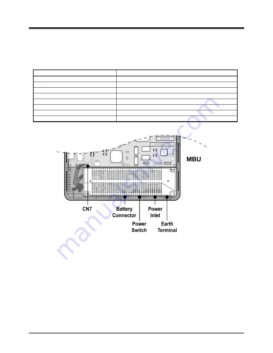
3.2.4 Power Supply Unit Installation 

Before installation, assure that the AC plug is not connected to an AC outlet.  The PSU is located at the left in the 
KSU and is pre-installed in the ARIA SOHO IP KSU.  The PSU provides three DC voltage power sources to MBU 
through the 7-pin connector, CN7. 


Description Specification 

AC Voltage Input 

100~240 Vac +/- 10 %  

AC Frequency 

47-63Hz 

AC Power Consumption 

90W 

AC Input Fuse 

2A @250Volt AC 

DC Output Voltage 

+5V/3A, -5V/0.2A, +27V/0.2A, +30/1.5A  

DC Input Voltage 

+24 Volt DC (+12VDC x 2ea) 

Battery Fuse 

5.0A @250Volt  

Battery Charging Current 

200mA 


FIGURE 3.2.4 PSU INSTALLATION 


Summary of Contents for ARIA SOHO IP

Page 1: ...ARIA SOHO IP Hardware Description and Installation Manual ...

Page 2: ... local telephone company may make changes in its communications facilities or procedures If these changes could reasonably be expected to affect the use of the ARIA SOHO IP or compatibility with the network the telephone company is required to give advanced written notice to the user allowing the user to take appropriate steps to maintain telephone service The ARIA SOHO IP complies with rules rega...

Page 3: ...ARIA SOHO IP Hardware Description and Installation Manual Issue 1 December 2008 Revision History ISSUE DATE CONTENTS OF CHANGES REMARK ISSUE 1 0 2008 12 Initial Release ...

Page 4: ...Capacity 10 3 KSU INSTALLATION 11 3 1 Pre Installation 11 3 1 1 Safety Installation Instructions 11 3 1 2 Installation precautions 11 3 1 3 Wiring Precautions 11 3 2 KSU Installation 12 3 2 1 Unpacking 12 3 2 2 KSU Exterior and Dimension 13 3 2 3 Opening and Closing the Front Cover 14 3 2 4 Power Supply Unit Installation 16 3 2 5 Frame Ground Connection 17 3 2 6 External Backup Battery Installatio...

Page 5: ...nit AAFU 46 4 5 2 Modem Function Unit MODU 47 4 5 3 CMU50PR Call Metering 50Hz and Polarity Reversal Detection Unit 47 4 5 4 CMU12PR Call Metering 12KHz and Polarity Reversal Detection Unit 47 5 TERMINAL CONNECTION AND WIRING METHOD 48 5 1 Terminal and Door Phone Models 48 5 1 1 Terminal Cabling Distance 50 5 1 2 Basic Terminal Connection 51 5 1 3 Connecting Additional Terminals 52 5 2 Cable Wirin...

Page 6: ... power company Do not allow anything to rest on the power cord Do not locate this product where the cord could be abused by people walking on it Do not overload wall outlets and extension cords as this can result in the risk of fire or electric shock Never push objects of any kind into this product through KSU slots or connectors as they may touch dangerous voltage points or short out parts that c...

Page 7: ...nd return this system to your dealer To prevent the risk of fire electric shock or energy hazard do not expose this product to rain or any type of moisture To protect PCB from static electricity discharge body static before touching connectors and or components by touching ground or wearing a ground strap WARNING Danger of explosion if battery is not correctly replaced Replace only with the same o...

Page 8: ...stem specifications and capacity Section 3 KSU Installation Describes detailed instructions for planning the installation site and procedures to install the ARIA SOHO IP System Section 4 Board Installation Describes detailed instructions for installing components of the ARIA SOHO IP Board Section 5 Terminal Connections and Wiring Method Describes the kinds of terminals maximum distance and other d...

Page 9: ...ersal Detection Unit CN Connector CO Central Office CPU Central Processing Unit CSB316 3 CO lines and 16 SLT interface board DC Direct Current DKTU Digital Key Telephone Unit DSP Digital signal processing DSS Direct Station Selection DTMF Dual Tone Multi Frequency EMI Electromagnetic Interference ESD Electrostatic Discharge ETS European Telecommunications Standards FSK Frequency shift keying GND G...

Page 10: ...exing TE Terminal Equipment TEGND Terminal Equipment Ground TX Transmitting signal UCD User Call Distribution UL Underwriters Laboratories UTP Unshielded Twisted Pair VR Voice Ring VT Voice Tip VMIU Voice Mail Interface Unit VOIB Voice Over Internet Protocol interface Board VOIP Voice over IP VOIU Voice Over Internet Protocol Interface Unit ...

Page 11: ...l PC application via LAN Modem RS 232C 9 Enhanced voice features 9 Simple installation efficient system management Remote admin software upgrade through LAN connection Remote admin software upgrade through PSTN modem 9 Value Added features Distinctive voice mail ADPCM 32 Kbps Basic CID CO SLT Function 8 Poly internal MOH 13 Music sources 2 1 1 System Connection Diagram The following Figure shows t...

Page 12: ...ersal Detection Unit 3 channels 3 CO Lines and 16 SLT Interface Board CMU50PR Call Metering 50Hz and Polarity Reversal Detection Unit 3 channels CMU12PR Call Metering 12KHz or 16KHz and Polarity Reversal Detection Unit 3 channels CSB316 SLU8 8 SLT Interface Unit Installed on CSB316 as a default SLIB8 8 SLT Interface Board Voice over IP Board 4ch VOIB VOIU Voice over IP unit 4ch PRI and 8 Hybrid In...

Page 13: ...Hz and Polarity Reversal Detection Unit 3 channels CHB308 CMU12PR Call Metering 12KHz or 16KHz and Polarity Reversal Detection Unit 3 channels 3 CO Lines and 16 SLT Interface Board CMU50PR Call Metering 50 Hz and Polarity Reversal Detection Unit 3 channels CMU12PR Call Metering 12KHz or 16KHz and Polarity Reversal Detection Unit 3 channels CSB316 SLU8 8 SLT Interface Unit Installed on CSB316 as a ...

Page 14: ...t 0dBm 600ohm External Paging Port 0dBm 600ohm Ring Detect Sensitivity 30Vrms 16 55Hz Frequency Deviation Less than 1 8 Signal Rise Time 5ms Tone Duration on time Min 50 ms Normally 100ms DTMF Dialing Inter digit Time Min 30ms Normally 100ms Pulse Rate 10PPS Pulse Dialing Break Make Ratio 60 40 or 66 33 Temperature 0 o C 40 o C Operating Environment Humidity 0 80 non condensing KSU 339mm W x 288mm...

Page 15: ...5 Intercom Links Non Blocking Paging All Call Internal 1 zone 5 zones Station Speed Dial 100 station 24 digits each 500 System Speed Dial 24 digits each 500 Last Number Redial 15 50 by admin programming 32 digits CO Line Group 8 8 Station Group 10 10 Conference 3 15 Party All ports are available Multi Conference 3 15 Party Max 3 groups Internal MOH 13 Music Sources 1 MBU 1 External MOH 1 MBU 1 Ext...

Page 16: ...ks or vibrations are frequent or strong Dusty places or places where water or oil may come into contact with the System Near high frequency generating devices such as sewing machines or electric welders On or near computers fax machines or other office equipment as well as microwave ovens or air conditioners Do not obstruct the openings on the top of the ARIA SOHO IP System Do not stack up the opt...

Page 17: ...ecember 2008 12 3 2 KSU Installation 3 2 1 Unpacking Open the box and verify that the items shown in Figure 3 2 1 are included FIGURE 3 2 1 CARTON CONTENTS Tie cable Anchor plug Screw Fuse CD manual Power cord Battery cable Mounting template Key Service Unit Relay connector Rubber feet ...

Page 18: ...ardware Description and Installation Manual Issue 1 KSU INSTALLATION December 2008 13 3 2 2 KSU Exterior and Dimension Figure 3 2 2 shows the exterior and dimensions of the KSU FIGURE 3 2 2 KSU EXTERIOR AND DIMENSION ...

Page 19: ...cember 2008 14 3 2 3 Opening and Closing the Front Cover 3 2 3 1 Opening the Front Cover 1 Open the Cord cover and turn the screws counter clockwise to loosen as shown in Figure 3 2 3 1 2 Lift the front cover in the direction of the arrow as shown FIGURE 3 2 3 1 OPENING THE FRONT COVER ...

Page 20: ...er into the slot on the KSU as shown in Figure 3 2 3 2 2 Then put the front cover down on the KSU in the direction of the arrow as shown 3 Turn the screws clockwise to tighten and close the Cord Cover as in the Figure FIGURE 3 2 3 2 CLOSING THE FRONT COVER NOTE Prior to operation the front cover of the ARIA SOHO IP must be closed and the screws tightened ...

Page 21: ... the KSU and is pre installed in the ARIA SOHO IP KSU The PSU provides three DC voltage power sources to MBU through the 7 pin connector CN7 Description Specification AC Voltage Input 100 240 Vac 10 AC Frequency 47 63Hz AC Power Consumption 90W AC Input Fuse 2A 250Volt AC DC Output Voltage 5V 3A 5V 0 2A 27V 0 2A 30 1 5A DC Input Voltage 24 Volt DC 12VDC x 2ea Battery Fuse 5 0A 250Volt Battery Char...

Page 22: ...rce refer to Caution FIGURE 3 2 5 GROUNDING THE KSU CAUTION The equipment should be connected to a socket outlet with a protective ground connection For ground wire green and yellow insulation is required and the cross sectional area of the conductor must be more than UL 1015 AWG 18 1 0mm It is recommended that the ground wire is shorter than 1m 3 28ft We dose not provide the ground wire Proper gr...

Page 23: ...d or if the battery voltage is too low to maintain full system operation The external batteries can maintain System operation as needed depending on several elements such as battery charge status condition and capacity of the batteries and System configuration number of Station ports CAUTION It is recommended to use an external backup battery fuse 5A 250V between the battery and the System Recomme...

Page 24: ... Wall Mounting 1 Install 3 anchor plugs in the wall using the mounting template included for accurate placement Figure 3 2 7 1A 2 Attach the mounting template using the 3 screws and anchors included 3 Hook the KSU onto the screws making sure that the System slides down securely Figure 3 2 7 1B Figure 3 2 7 1A Mounting Template ...

Page 25: ...ARIA SOHO IP Hardware Description and Installation Manual Issue 1 KSU INSTALLATION December 2008 20 FIGURE 3 2 7 1B KSU WALL MOUNTING NOTE Be careful not to drop the KSU ...

Page 26: ...g To attach the ARIA SOHO IP System to the rack 1 Attach the rack bracket to the bottom of the ARIA SOHO IP System as shown in Figure 3 2 7 2 and attach it to the System securely by tightening the screws clockwise 2 Affix the bracket with the 4 screws provided Figure 3 2 7 2 FIGURE 3 2 7 2 RACK BRACKET AND RACK MOUNTING ...

Page 27: ...OHO IP System on a flat surface do the following procedure 1 To attach the rubber feet to the bottom of the ARIA SOHO IP System as shown in Figure 3 2 7 3 first remove the backing paper from the sticker on the rubber feet 2 After attaching the rubber feet to the BKSU and EKSU mount the EKSU onto the BKSU firmly FIGURE 3 2 7 3 DESKTOP MOUNTING ...

Page 28: ...8 23 3 3 Expansion KSU Installation 3 3 1 Unpacking Open the box and verify that the items shown in Figure 3 3 1 are included Figure 3 3 1 Carton Contents Tie cable Anchor plug Screw Fuse Power cord Battery cable Mounting template Key Service Unit Link cable Relay connector Rubber feet Jump wire ...

Page 29: ...ble to connect the Basic KSU to the Expansion KSU 4 To fix the link cable securely turn the screw clockwise to tighten and then tie the link cable with tie cable FIGURE 3 3 2 EXPANSION KSU TO BASIC KSU CONNECTION NOTE When AC Power was failed the last SLT port on EMBU will be connected to CO1 automatically Even though the power of EKSU is turned off while both systems BKSU and EKSU are working pro...

Page 30: ...le 3 3 3 1 Wall Mounting 1 It is recommended to install the Expansion system very close in proximity to the Basic System within 5cm 2 Install 3 anchor plugs in the wall using the mounting template included for accurate placement Figure 3 3 3 1A The KSU can be mounted either vertically or horizontally 3 Insert the included 3 screws to 3 anchor plugs FIGURE 3 3 3 1A MOUNTING TEMPLATE 4 Hook the Expa...

Page 31: ...ARIA SOHO IP Hardware Description and Installation Manual Issue 1 KSU INSTALLATION December 2008 26 FIGURE 3 3 3 1B EXPANSION KSU WALL MOUNTING NOTE Be careful not to drop the KSU ...

Page 32: ...ansion system very close in proximity to the Basic System 2 Attach the rack bracket to the bottom of the ARIA SOHO IP system as shown in Figure 3 3 3 2A and attach it to the System securely by tightening the screws clockwise FIGURE 3 3 3 2A RACK BRACKET 3 To attach the ARIA SOHO IP System to the rack affix the bracket with the 4 screws provided Figure 3 3 3 2B ...

Page 33: ...ARIA SOHO IP Hardware Description and Installation Manual Issue 1 KSU INSTALLATION December 2008 28 FIGURE 3 3 3 2B KSU RACK MOUNTING ...

Page 34: ...s To discharge static touch a grounded object or wear a grounding strap Insert boards carefully to avoid bending connector pins male pins on MBU EMBU and board damage from power shortage caused by misaligning To install the Board perform the following Steps 1 Before inserting the Board remove the cover plate of slot as shown in 1 of Figure 4 1 2 Holding the board as shown in 2 of the diagram caref...

Page 35: ... DKT and SLT interface circuits Ring Generation circuit External Relay contact for LBC or General purpose Alarm Detection circuit External Page port Internal MOH circuit External MOH port Peripheral Device Decoding circuit Master Clock Generation circuit PFT circuit CO1 Ù the last SLT port STA8 RS 232C Interface circuit LAN Interface circuit PCM Voice Processing circuit ACT2 ASIC voice switching i...

Page 36: ...IB8 PRHB8 installation 50Pins CN4 MODU Installation 20Pins CN5 VMIU AAFU Installation 32Pins CN9 CN10 CMU50PR CMU12PR Installation 6 8Pins CN14 VOIB Installation 16Pins CN6 JTAG Port for Emulator For Test CN7 PSU Connection 5V 5V 30V 7Pins CN8 RS 232C Port Connection 9Pins MJ1 3 CO Lines Connection 3Arrays MJ2 1 1 DKT or Alarm sensor MJ2 MJ2 2 8 7 DKTs or 7 SLTs Connection 8Arrays CN13 External Re...

Page 37: ...IN NUMBER NO SIGNAL NAME 1 N A 2 DKT T 3 4 ALARM_Detection 5 DKT R RJ11 6 N A MBU MJ2 2 3 4 5 6 7 8 CONNECTOR PIN NUMBER NO SIGNAL NAME 1 N A 2 DKT T 3 4 SLT T SLT R 5 DKT R RJ11 6 N A NOTE When installing DKT or SLT on Hybrid Ports MJ2 2 3 4 5 6 7 8 keep the above pin assignment Otherwise the DKT or SLT will not operate normally TERMINAL DKT CONNECTOR PIN NUMBER NO SIGNAL NAME 1 N A 2 RING 3 4 Re...

Page 38: ...to initialize the default System database Once the database has been initialized switch 1 4 should be placed in the OFF position to protect the database After putting the SW2 lithium battery switch ON to protect the RAM RTC data install the option boards to the MBU NOTE The SW2 DIP switch should be turned ON to protect the System database in case of power failure As needed replace the batteries wi...

Page 39: ... purpose Peripheral Device Decoding circuit Master Clock Generation circuit PFT circuit CO1 Ù the last SLT port STA8 PCM Voice Processing circuit with ACT2 ASIC voice switching including DSP device for PCM tone generation and PCM gain control FIGURE 4 3A EMBU NOTE When AC Power was failed the last SLT port on EMBU will be connected to CO1 automatically Even though the EKSU power is turned off whil...

Page 40: ...d Table FIGURE 4 3B EMBU CONNECTION PORTS CONNECTOR MODULAR JACK SWITCH FUNCTIONS SWITCH CONNECTOR FUNCTIONS REMARK CN1 KSU Connection from Basic KSU with Link cable 50Pins CN2 CO and Extension board CHB308 CSB316 SLIB8 installation 50Pins CN9 CN10 CMU50PR CMU12PR installation 6 8 Pins CN13 External Relay contact 4 Pins CN7 PSU connection 7Pins MJ1 3 CO connection 3 Arrays MJ2 8 DKTs or 8SLTs conn...

Page 41: ...AME 1 N A 2 DKT T 3 4 SLT T SLT R 5 DKT R RJ11 6 N A NOTE When installing the DKT or SLT on Hybrid Ports MJ2 1 2 3 4 5 6 7 8 keep the above pin assignment Otherwise the DKT or SLT will not operate normally TERMINAL DKT CONNECTOR PIN NUMBER NO SIGNAL NAME 1 N A 2 RING 3 4 Reserved 5 TIP RJ11 6 N A TERMINAL SLT CONNECTOR PIN NUMBER NO SIGNAL NAME 1 2 N A 3 4 TIP RING RJ11 5 6 N A 4 3 1 2 CN13 Pin As...

Page 42: ...and 8SLT or 8 DKT RJ45 RJ11 PRI and 8 Hybrid interface PRI 8 wire DKT 4 wire SLT 2 wire 4 4 1 CHB308 3 CO Line and 8 Hybrid Interface Board The CHB308 can be installed on the CHB308 CSB316 SLIB8 CN2 connector of the MBU or EMBU and provides 3 CO PBX Loop Start CO Line interfaces that support Pulse DTMF signaling Each interface contains ring and loop current circuits A D and D A conversions and pul...

Page 43: ...1 2 Add On Board CMU50PR Call Metering 50 Hz Polarity Reversal Detection unit The CMU50PR provides 3 channels Call Metering detection for 50Hz and provides 3 channels of Polarity Reversal Detection for call metering It can be installed on the MBU EMBU CHB308 or CSB316 4 4 1 3 Add On Board CMU12PR Call Metering 12KHz or 16KHz Polarity Reversal Detection unit The CMU12PR provides 3 channels Call Met...

Page 44: ...U and provides 16 possible SLT interfaces It can generate FSK signals for outgoing caller ID DTMF signal for outgoing caller ID FIGURE 4 4 2 1 CSB316 4 4 2 1 Modular Jack Pin Assignment CSB316 MJ1 1 2 3 CONNECTOR PIN NUMBER NO SIGNAL NAME 1 2 N A 3 4 CO T CO R RJ11 5 6 N A CSB316 MJ2 1 2 3 4 5 6 7 8 CONNECTOR PIN NUMBER NO SIGNAL NAME 1 N A 2 SLT T 3 4 SLT T SLT R 5 SLT R RJ11 6 N A NOTE The CSB31...

Page 45: ... Polarity Reversal detection for call metering It can be installed on the MBU EMBU CHB308 or CSB316 4 4 2 3 Add On Board CMU12PR Call Metering 12KHz or 16KHz Polarity Reversal Detection unit The CMU12PR provides 3 channels Call Metering detection for 12 KHz or 16 KHz and provides 3 channels of Polarity Reversal Detection for call metering It can be installed on the MBU EMBU CHB308 or CSB316 4 4 2 ...

Page 46: ...led on the CHB308 CSB316 SLIB8 CN2 connector of the MBU or EMBU and provides 8 possible SLT interfaces It can generate FSK signals for outgoing Caller ID DTMF signals for outgoing Caller ID FIGURE 4 4 3 SLIB8 4 4 3 1 Modular Jack Pin Assignment SLIB8 MJ2 1 2 3 4 5 6 7 8 CONNECTOR PIN NUMBER NO SIGNAL NAME 1 N A 2 Reserved 3 4 SLT T SLT R 5 Reserved RJ11 6 N A ...

Page 47: ... one 1 VOIB and VOIU provides additional four 4 VoIP channels Item Specification LAN Interface 10 Base T Ethernet IEEE 802 3 Speed 10 Mbps Auto Negotiation Duplex Half Duplex or Full Duplex Auto Negotiation VoIP Protocol H 323 Revision 2 Voice Compression G 711 G 726 G729 G 723 1 Voice Fax Switching T 38 Echo cancellation G 165 4 4 4 1 Various switches and connectors functions Switch Connector Fun...

Page 48: ...ion LED ON Busy OFF Idle LD8 Channel8 Seize indication LED ON Busy OFF Idle LD9 VOIU DSP operation status LED ON Normal OFF Fail LD10 VOIB DSP operation status LED ON Normal OFF Fail LD11 DSP HINT interrupt LED ON Active OFF Idle MJ1 LD2 yellow Speed Status LED OFF 10Mbps MJ1 LD1 green orange Link Status LED ON Link Toggle Data transfer 4 4 4 2 Pin assignment Connector Pin Number NO SIGNAL NAME FU...

Page 49: ... to the signaling channel the other TSs are available for allocation to the B channel CEPT frame has four signaling bits A B C and D Signaling bits for all 30 information channels are transmitted in timeslot 16 of frames 1 15 The PRHB8 supports pulse dialing DTMF dialing and MFC R2 register signaling based on ITU T Recommendation Q 440 480 Data bit clock are transmitted by TE slave The ARIA SOHO I...

Page 50: ...JTAG port for DSP emulator CN6 CN7 Connector for SLU8 LED Indications Status LED Function ON OFF Remark LD1 In use indication of PRI In use Idle LD2 CRC CRC error Normal LD3 Remote Alarm Indication RAI error Normal LD4 Multi use MF error Normal LD5 AIS AIS error Normal LD6 Loss of signal from the line LOS Normal LD7 Not use Always OFF LD8 Normal operation indication Blink LD9 PLL clock selection E...

Page 51: ...led on the VMIU AAFU connector CN5 of the MBU and provides System Announcement and ACD UCD Announcements FIGURE 4 5 1 VMIU AAFU VMIU DESCRIPTION ITEM DETAIL Channel 4 Channels Max Record Time System Greeting system announcement User Record Time 123 Min 24 Min 99 Min Max Number of User Voice Messages 800 NOTE User greetings are stored in N and Flash memory and will not be lost by System power OFF o...

Page 52: ... The Call Metering 50Hz and Polarity Reversal Detection Unit CMU50PR provides 3 Call Metering Detection circuits for 50Hz and provides 3 channels of Polarity Reversal Detection for Call Metering or signaling It can be installed on the MBU EMBU CHB308 or CSB316 4 5 4 CMU12PR Call Metering 12KHz and Polarity Reversal Detection Unit The Call Metering 12KHz or 16KHz and Polarity Reversal Detection Uni...

Page 53: ...he ARIA SOHO IP MBU EMBU CHB308 CSB316 PRHB8 as listed in the Table and show below MODEL DESCRIPTION LDP 7208D 2 Line LCD 8 Flexible Button Display LDP 7224D 3 Line LCD 24 Flexible Button Display LDP 7048DSS 48 Button DSS Console LIP 7008D 2 Line LCD 8 Flexible Button Display LIP 7016D 3 Line LCD 16 Flexible Button Display LIP 7024D 3 Line LCD 24 Flexible Button Display LIP 7024LD Large LCD 24 Fle...

Page 54: ...SOHO IP Hardware Description and Installation Manual Issue 1 TERMINAL CONNECTION AND WIRING METHOD December 2008 49 LIP 7008D LIP 7016D LIP 7024D LIP 7024LD LIP series keysets LIP 7048DSS LDP 7048DSS LDP DPB ...

Page 55: ...ARIA SOHO IP Hardware Description and Installation Manual Issue 1 TERMINAL CONNECTION AND WIRING METHOD December 2008 50 5 1 1 Terminal Cabling Distance FIGURE 5 1 1 TERMINAL CABLING DISTANCE ...

Page 56: ...ollowing illustrates how to connect the DKT to your System FIGURE 5 1 2 DKT AND DSS CONNECTION PIN ASSIGNMENT CONNECTOR PIN NUMBER NO SIGNAL NAME 1 N A 2 DKT T 3 4 Reserved 5 DKT R RJ11 6 N A 5 1 2 2 SLT The following illustrates how to connect the SLT to your System FIGURE 5 1 3 SLT CONNECTION PIN ASSIGNMENT CONNECTOR PIN NUMBER NO SIGNAL NAME 1 2 N A 3 4 TIP RING RJ11 5 6 N A ...

Page 57: ... 1 3 1 External Music Source Wiring The MBU accommodates one external music port through a PJ1 RED audio jack 5 1 3 2 Relay Contacts The MBU EMBU provides 2 relay contact that is used for loud bell or general purpose through pin No 1 4 of CN13 5 1 3 3 External Paging Port wiring The MBU supports one external paging port through a PJ2 BLUE audio jack 5 1 3 4 Alarm Detection Wiring The MBU provides ...

Page 58: ... BKSU and EKSU have been installed correctly 2 Connect cables to the CO STA port and the MOH RS 232C ports as shown in Figure 5 2 1 3 Connect the Power cord and the Battery cable 4 Remove plastic filter pieces 5 Tie all the cables and the Power cord if desired through the tie slot at the bottom right side of the KSUs using the tie cable provided 6 Close the cover of the KSUs and close the cord cov...

Page 59: ...rrectly 2 Connect cables to the CO STA port and the MOH RS 232C ports as shown in Figure 5 2 2 3 Connect the Power cord and the Battery cable 4 Remove plastic filter pieces 5 Tie all the cables and the Power cord if desired through the tie slot at the bottom right side of the KSUs using the tie cable provided 6 Close the cover of the KSUs and close the cord cover FIGURE 5 2 2 RACK MOUNT WIRING ...

Page 60: ...owing Steps 1 The DIP switch SW2 should be turned ON prior to installing the MBU to protect the System data in case of power failure 2 Check the DIP switch SW1 of the MBU to All ON 3 Plug the AC power cord into the ARIA SOHO IP System and AC outlet 4 Program the Nation Code PGM100 as applicable 5 Reset the ARIA SOHO IP System 6 Set the 4th pole SW1 of the MBU OFF when the System operates normally ...

Page 61: ...e active in the programming mode at any one time When in programming mode Station 100 does not operate as a normal telephone but instead works as a programming instrument with all of the buttons redefined The keys of the dial pad are used to enter the various data fields to enter numerical information Flexible Buttons The 24 buttons located at the right side of the phone are used to indicate a spe...

Page 62: ... dial a confirmation tone should be heard 3 Enter the Admin password if the password has been set a confirmation tone should be heard indicating that the Station is in Admin Programming mode 4 Each program is accessed by pressing the TRANS PGM button the following should display ENTER PGM NUMBER 5 Dial the desired three digit program number If an error is made while entering data the TRANS PGM but...

Page 63: ...ming 6 2 3 1 Location PGM Nation Code and Site Name PGM 100 NOTE The 4th pole of the DIP switch SW1 on the MBU must be turned ON Nation Code To program the Nation Code perform the following Steps 1 Press the TRANS PGM button PGM number 100 then FLEX1 55 Nation Code for Brazil 2 Press the HOLD SAVE button to accept the change 3 Now Rest ARIA SOHO IP to initialize Database for Nation 4 Set the 4th p...

Page 64: ...es 63 Portugal 351 Qatar 974 Saudi Arabia 966 Senegal 221 Singapore 65 South Africa 27 Spain 34 Sri Lanka 94 Swaziland 268 Sweden 46 Switzerland 41 TELKOM 27 Thailand 66 Tunisia 216 Turkey 90 U A E 971 United Kingdom 44 Uruguay 598 Venezuela 58 Vietnam 84 Y A R 967 TELSTRA 61 6 2 3 2 Board Assignment PGM 101 To use CO line extension line and board first of all if the code of these boards is regist...

Page 65: ...tered by slot number order User can reassign slot order of each CO Line or extension line to appropriate to user circumstance For example if CO Line board LCOB is installed at Slot 5 and at Slot 6 CO line 01 03 becomes CO line of Slot 5 But if installing each CO line board on the contrary CO line 01 03 becomes CO line of Slot 6 COL Board 1 Press the TRANS PGM button PGM number 103 2 Press FLEX1 bu...

Page 66: ...100 101 102 103 TRANS PGM 105 000 001 002 003 100 101 102 103 Station Number Assign Four station numbers correspond to the 4 port numbers The Station number length is in the range of 2 digits through 4 digits There are two methods for changing the station number Dial two station numbers Dial the range of the start and end Station numbers The LCD will show the dialed range value Press the HOLD SAVE...

Page 67: ...4 MSG Wait Call Back Answer 557 15 Speed Dial Access 558 16 Cancel DND CFW Pre Selected MSG Features 559 17 SLT Hold 560 18 Reserved 19 Reserved 20 SLT Program Mode Select 563 21 ACD Reroute 564 To program Flexible numbering using PGM 107 perform the following Steps 1 Press the TRANS PGM button 107 2 Enter the desired code refer to Table 3 Press the HOLD SAVE button to accept changes FLEXIBLE NUMB...

Page 68: ...08 2 Press the FLEX1 Button 3 Enter the desired IP Name up to 15 characters refer to the section 6 2 3 1 DKTU button map for Character 4 Press the HOLD SAVE button to accept changes Server IP Address 1 Press the TRANS PGM button 108 2 Press the FLEX2 Button 3 Enter the server IP Address 12 digits ex 192168131154 for IP 192 168 131 154 4 Press the HOLD SAVE button to accept changes CLI IP Address 1...

Page 69: ...of DKT and System Check the distance between the MBU EMBU CHB308 CSB316 PRHB8 and the DKT DKTU DOES NOT OPERATE Bad DKT Plug the DKT into another extension port that has been verified as working If the DKT still does not work properly replace the DKT Bad MBU EMBU CHB308 CSB316 PRHB8 or SLIB8 board Exchange the board for one in good working condition SLT DOES NOT OPERATE Bad connection between the ...

Reviews: