background image

Safety

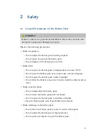
2.2

Tools

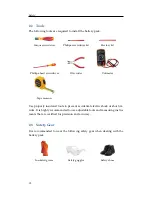
The following tools are required to install the battery pack:

Torque screwdriver

Phillips-screwdriver bit

Hex-key bit

Phillips-head screwdriver

Wire cutter

Voltmeter

Tape measure

Use properly insulated tools to prevent accidental electric shock or short cir-
cuits. It is highly recommended to use adjustable tools and measuring instru-

ments that are certified for precision and accuracy.

2.3

Safety Gear

It is recommended to wear the following safety gear when dealing with the
battery pack.

Insulated gloves

Safety goggles

Safety shoes

12

Summary of Contents for 6.4 EX

Page 1: ...Residential Energy Storage Unit 6 4 EX Battery Pack For Photovoltaic Systems Installation Manual September 2015 Edition 2 ...

Page 2: ...mmendations or safety procedures described in this manual contact LG Chem immediately for advice and clarification NOTE The information included in this document is accurate at the time of publi cation However this product is subject to change without prior notice In addition the illustrations in this document are meant only to help explain system configuration concepts and installation instructio...

Page 3: ...Expansion battery pack 14 3 Installation 15 3 1 Installation Location 15 3 2 Installing the Main Battery Pack 16 Securing the battery pack to a wall 16 Connecting the battery pack to the inverter 18 3 3 Installing the Expansion Battery Pack 22 Connecting an expansion pack to the main pack 22 Securing the expansion pack to a wall 27 3 4 Checking Before Operation 29 Circuit breaker switch 29 Circuit...

Page 4: ...3 Wet Batteries 35 5 4 Damaged Batteries 35 6 Warranty 36 6 1 Warranty Coverage 36 6 2 Limitation of Liability 36 6 3 Contact Information 36 A Technical Information 37 A 1 Main Battery Pack 38 A 2 Expansion Battery Pack 39 A 3 Main Pack plus 1 Expansion Pack 39 A 4 Main Pack plus 2 Expansion Packs 39 A 5 Compatible Inverters 40 4 ...

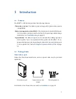
Page 5: ...ty The battery capacity can be increased by adding expansion battery packs Up to two expansion battery packs can be added An ex pansion battery pack can be purchased either with the main battery pack or as a separate unit See Installing the Expansion Battery Pack on page 22 1 2 Package Items Main battery pack Items other than those listed below such as a power cable may be provided separately Sta ...

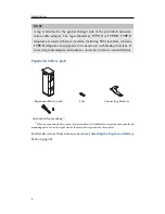
Page 6: ...y with Nedap inverters If the wrong cable adapter is identified contact LG Chem or your distributor Expansion battery pack Expansion battery pack Fuse Connecting brackets Anchor bolt for mounting1 1 When an expansion battery pack is later installed if it is difficult to reuse the anchor bolt and mounting bolt used on the right side of the main battery pack use these bolts For details on how these ...

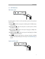
Page 7: ...it orange Normal operation When the main pack is in normal operation the Sta tus indicator is lit green Charge in progress While the main pack is charging the Charge Dis charge indicator is lit red Discharge in progress While the main pack is discharging the Charge Discharge indicator is lit green Alarm When the main pack is in a warning or fault state the Status indicator alternately flashes gree...

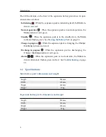
Page 8: ...See Starting the Battery Pack on page 31 Charge in progress While the expansion pack is charging the Charge Discharge indicator is lit red Discharge in progress While the expansion pack is discharging the Charge Discharge indicator is lit green Alarm When the expansion pack is in a fault state the Status in dicator alternately flashes green and red See Troubleshooting on page 32 1 4 Specifications...

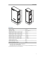
Page 9: ... 252 A h Nominal energy with no expansion pack 6 4 kW h Nominal energy with 1 expansion pack 9 6 kW h Nominal energy with 2 expansion packs 12 8 kW h Nominal charge current1 42 A Nominal discharge current2 42 A Maximum discharge current3 110 A 1 in constant current constant voltage charging mode 2 in constant current discharging mode 3 If the temperature inside the battery pack rises the charging ...

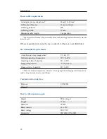
Page 10: ...r distributor Environmental requirements Available operating temperature1 0 C to 40 C Optimal operating temperature 15 C to 30 C Operating relative humidity 25 to 95 Storage temperature 30 C to 50 C Storage relative humidity 25 to 95 1 When the ambient temperature is below 10 C charging and discharging current may be de rated to keep the battery safety and lifetime Communication interface Protocol...

Page 11: ...es in excess of 50 C Do not place the battery pack near a heat source such as a fireplace Do not expose the battery pack to direct sunlight Do not allow the battery connectors to touch conductive objects such as wires Risks of electric shock Do not disassemble the battery pack Do not touch the battery pack with wet hands Do not expose the battery pack to moisture or liquids Keep the battery pack a...

Page 12: ...tmeter Tape measure Use properly insulated tools to prevent accidental electric shock or short cir cuits It is highly recommended to use adjustable tools and measuring instru ments that are certified for precision and accuracy 2 3 Safety Gear It is recommended to wear the following safety gear when dealing with the battery pack Insulated gloves Safety goggles Safety shoes 12 ...

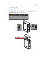
Page 13: ... battery pack The nameplate is attached to the right side of the main battery pack and warn ing labels are attached to the top and left side Sta tus Ch arg e Dis cha rge RE SU 6 4 R 1 1 4 Sta tus Ch arg e Dis cha rge RE SU 6 4 R 13 ...

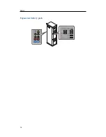
Page 14: ...Safety Expansion battery pack RESU 6 4EX EXP 9 63 2 1 1 4 14 ...

Page 15: ...ls The ambient temperature is within the range from 0 C to 40 C The temperature and humidity is maintained at a constant level There is minimal dust and dirt in the area CAUTION If the ambient temperature is outside the operating range the battery pack stops operating to protect itself The optimal temperature range for the bat tery pack to operate is 15 C to 30 C Frequent exposure to harsh tempera...

Page 16: ... of the battery pack 20 mm Make sure to leave a space of at least 20 mm between the battery pack and the wall A clearance of at least 20 mm must be left around the battery pack for proper cooling CAUTION Make sure that the battery pack is at all times exposed to the ambient air The battery pack is cooled by natural convection If the battery pack is entirely or partially covered or shielded it may ...

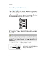
Page 17: ... rge Sta tus Cha rge Dis cha rge RE SU 6 4 R Sta tus Cha rge Dis cha rge Sta tus Cha rge Dis cha rge 2 Drive the anchor bolts through the mounting brackets into the holes 3 Tighten the nuts to a torque of 6 N m Statu s Ch arge Disch arge RE SU 6 4 R 4 There are holes for mounting brackets on both edges of the back Cut the re movable pieces out of the holes using a wire cutter 5 Secure the mounting...

Page 18: ... the battery pack to the inverter CAUTION Make sure that the inverter is turned off before connecting the battery pack to the inverter To connect the cables coming from the inverter to the battery pack take the following steps Status Ch arge Discha rge RES U 6 4 R 1 Remove the top cover Hold both sides of the top cover and pull it upwards 2 Remove the protective tape that covers the circuit breake...

Page 19: ...switch is in the OFF position 4 Cut the removable pieces out of the grommets on the upper part of the left side 5 Connect the provided cable adapter to the communication port and then connect the communication cable coming from the inverter to the cable adapter through the right grommet 19 ...

Page 20: ...nect the power ca bles to the terminal block through the grommets a Remove the terminal cover plate which is placed over the terminal block to protect it b Connect the negative cable to the left terminal and the positive cable to the right terminal Tighten the hex socket screws to a torque of 6 N m c Restore the terminal cover plate NOTE If you have an expansion battery pack to be installed do not...

Page 21: ...e pre operation checks de scribed in Checking Before Operation on page 29 9 Perform the procedure described in Starting the Battery Pack on page 31 Status Ch arge Discha rge RES U 6 4 R 10 Restore the top cover Press down on the top cover until it locks in place 21 ...

Page 22: ...Sta tus Cha rge Dis cha rge Sta tus Cha rge Dis cha rge Sta tus Cha rge Dis cha rge RE SU 6 4 R Sta tus Cha rge Dis cha rge Connecting an expansion pack to the main pack CAUTION Make sure that the inverter is turned off before installing the expansion battery pack To connect an expansion battery pack to the main battery pack take the fol lowing steps Status Ch arge Discha rge RES U 6 4 R 1 Remove ...

Page 23: ...that the indicators on the front are off If the main pack has been operating it would take 60 seconds at maximum for the indicators to turn off Status Ch arge Discha rge RES U 6 4 R 3 Cut the removable pieces out of the grommets on the upper part of the right side 4 Remove the top cover from the expan sion battery pack 23 ...

Page 24: ...ld the bracket in place and tighten the screw in the left hole of the bracket to a torque of 2 N m 6 Loosen the screw in the corresponding position of the expansion pack NOTE When connecting an expansion pack to another one use the right hole of the connecting bracket 7 Insert the cables coming from the expansion pack into the main pack through the grommets 24 ...

Page 25: ...10 Connect the cables to the connectors 1 The connector on the left supplies power to the expansion pack for operation 2 The main pack communicates with the expansion pack through the port in the middle 3 The expansion pack charges and discharges through the connector on the right 11 Attach the terminal resistor detached from the main pack to the unused port on the right side of the expansion pack...

Page 26: ... Hold the bracket in place and tighten the screw to a torque of 2 N m 13 Install the fuse in the expansion pack a Pull the fuse holder upwards to open it b Insert the fuse into the fuse holder c Restore the fuse holder 14 Restore the top cover of the expansion pack 26 ...

Page 27: ... of the main pack If you have another expansion pack repeat the aforementioned steps to con nect the first expansion pack to the second one Securing the expansion pack to a wall Status Charge Discharge RESU 6 4 R Status Charge Discharge Status Charge Discharge RESU 6 4 R Status Charge Discharge Status Charge Discharge Secure the right side of the expansion battery pack to the wall using a mount in...

Page 28: ...Installation bracket on the right side of the main battery pack For details how to install mounting brackets see Securing the battery pack to a wall on page 16 28 ...

Page 29: ... the ON position If the switch is in the Trip posi tion between the ON and OFF positions move it to the OFF position and then to the ON position If the switch moves by itself to any of the other positions contact LG Chem or your distributor Circuit breaker s trip button Status Ch arge Discha rge RES U 6 4 R Make sure that the circuit breaker switch is put in the ON position and then push the circu...

Page 30: ...ircuit breaker switch is put in the Trip position and then measure the voltage If the volt age is higher than 0 V contact LG Chem or your distributor 2 Move the circuit breaker switch to the ON position and then measure the voltage If the voltage is lower than 36 V contact LG Chem or your distrib utor 30 ...

Page 31: ...conds If it stays red contact LG Chem or your distributor The expansion pack takes around 65 seconds to check itself for proper operation after it has been initialized After that the Status indicator may begin flashing green The expansion pack is not operational until the voltage level of the main pack becomes the same as that of the ex pansion pack As long as the two voltage levels are not the sa...

Page 32: ...t LG Chem or your distributor in this case A warning state is triggered when a condition such as voltage or temperature is beyond its design limitations The main pack s BMS periodically reports its operational state to the inverter There are two abnormal states Warning When the main pack is likely to become faulty it goes into a warn ing state When a warning is reported the inverter shows the warn...

Page 33: ...k If an expansion battery pack is installed check the indicators on its front to determine in what state it is Status Charge Discharge Red Green1 Off Successfully initialized Red Red Off Initialization failed2 Green Green Discharging in normal state Green Red Charging in normal state Green Off Waiting in normal state Flashing Green Off Standby state Flashing Red Green Off Protection mode2 Off Off ...

Page 34: ...s Rinse eyes with flowing water for 15 minutes and seek medical attention Contact with skin Wash the affected area thoroughly with soap and water and seek medical attention Ingestion Induce vomiting and seek medical attention 5 2 Fire In case of fires it is recommended to have an ABC or carbon dioxide extinguisher WARNING The battery pack may catch fire when heated above 150 C If a fire breaks out...

Page 35: ...ccess it Contact LG Chem or your distributor for technical assistance 5 4 Damaged Batteries Damaged batteries are dangerous and must be handled with the utmost care They are not fit for use and may pose a danger to people or property If the battery pack seems to be damaged pack it in its original container and then return it to LG Chem or your distributor CAUTION Damaged batteries may leak electro...

Page 36: ...t result from the following causes Improper transportation or storage Incorrect installation Operating the product in an inappropriate environment Incorrect or inappropriate operation Insufficient ventilation Failure to adhere to safety warnings or instructions Repairs or modifications performed by unauthorized personnel Inverter failure or overcurrent Force majeure events External influences such...

Page 37: ...uct configuration Product code Main battery pack RESU 6 4 EX R48126P2S Expansion battery pack RESU 6 4 EX EXP R4863P2B Main pack 1 expansion pack RESU 6 4 EX SYS1 R48189P2S Main pack 2 expansion packs RESU 6 4 EX SYS2 R48252P2S 37 ...

Page 38: ...terface CAN 2 0B Dimensions 406 mm 165 mm 664 mm Weight 60 kg Available operating temperature2 0 C to 40 C Optimal operating temperature 15 C to 30 C Storage temperature 30 C to 50 C Cooling Natural convection Battery pack safety CE TUV IEC 62619 RCM Battery cell safety IEC 62133 UN number UN 3481 Hazardous materials classification Class 9 UN transportation testing requirements UN 38 3 Internation...

Page 39: ...ions 230 mm 165 mm 664 mm Weight 32 kg A 3 Main Pack plus 1 Expansion Pack Nominal capacity 189 A h Nominal energy 9 6 kW h Dimensions 636 mm 165 mm 664 mm Weight 92 kg A 4 Main Pack plus 2 Expansion Packs Nominal capacity 252 A h Nominal energy 12 8 kW h Dimensions 866 mm 165 mm 664 mm Weight 124 kg 39 ...

Page 40: ... multiple battery packs contact your installer inverter manufac turer or LG Chem for consultation SMA Model Backup Number of phases1 Compatible with RESU 6 4 EX Sunny Island 3 0M O 1 O Sunny Island 3 0M O 3 X Sunny Island 3 0M X 1 O Sunny Island 3 0M X 3 X Sunny Island 4 4M O 1 O Sunny Island 4 4M O 3 X Sunny Island 4 4M X 1 O Sunny Island 4 4M X 3 X Sunny Island 6 0H 11 O 1 O Sunny Island 6 0H 11...

Page 41: ...Technical Information Nedap Model Compatible with RESU 6 4 EX PR50SB BU O PR37SB BU O PR30SB BU O Sungrow Model Compatible with RESU 6 4 EX SH5k O 41 ...

Page 42: ...Keep this manual for later use LG Chem LG Twin Tower 128 Yeoui daero Yeongdeungpo gu Seoul 07336 Korea ...

Reviews: