background image

35

Wear Parts and Causes of Damage

Wear Part

Cause of Damage

Tooling

The Tooling can become chipped or broken. Lead times 
for a new set of Tooling can take as long as 6-8 weeks, 
so LFA recommends having a spare set or two.

Fill Tray

On the RTP 118

®

, the Fill Tray spreads the powder 

over the Die Table and into the Die bores. It is formed 
from cast brass and is designed to wear. It protects the 
Turret/Die Table and the Tooling. If this part is damaged 
by a Die sitting above the Die Table, it is possible to 
refinish it using a flat stone, some oil, and 3000 grit 
sandpaper. Eventually when the "gates" underneath are 
so small that powder is unable to pass through smoothly, 
or if there is a catastrophic failure, this part will need to 
be replaced.

Fill Tray Scrapers

One Fill Tray Scraper is used to take off the excess 
powder from the Die Table after the Dosing Cam has 
forced out the powder. The other Fill Tray Scraper is 
used to aid in tablet ejection. These parts can become 
damaged if a Die is protruding from the Die Table or if a 
Lower Punch jumps up from the Dosing Cam. To reduce 
waste, these parts will need to be replaced if damaged.

Ejection Cam

The Ejection Cam ejects the tablets at the correct 
moment in the Turret's cycle. This part is not able to be 
tuned and is fixed in place. Over time this part can wear, 
and the tablet's ejection point can get lower until they 
are not ejecting correctly from the Die bores. The three 
main causes of this are: 1) tight Lower Punches due 
to buildup of excess fines in powder, 2) high ejection 
forces that are caused by sticky powders clinging 
to the Die bore's wall, and 3) powder that mixes with 
oil/grease, which creates a sandpaper effect on the 
Ejection Cam.

Fill Cam

The Fill Cam pulls down the Lower Punches to fill the 
Die bores with powder. This part is built from brass and 
is designed to wear to protect the Tooling and the press. 
The main causes of a worn Fill Cam are: 1) tight Lower 
Punches due to buildup of excess fines in powder, 2) 
use of incorrect Tooling with the wrong head profile, and 
3) powder that mixes with oil/grease, which creates a 
sandpaper effect on the Fill Cam.

Dosing Cam

The Dosing Cam is used to calibrate the press to 
produce the desired tablet weight. This is done by 
pushing excess powder out of the Die bore after it has 
been filled. The main causes of a worn Dosing Cam are: 
1) Tight Lower Punches due to buildup of excess fines in 
powder, 2) use of incorrect Tooling with the wrong head 
profile, and 3) powder that mixes with oil/grease, which 
creates a sandpaper effect on the Dosing Cam.

Upper/Lower Pressure Cam

The Roller Cams apply all the pressure onto the Tooling. 
If these become worn, it can cause damage to the 
tops of the Tooling and affect tablet hardness and 
consistency. This is predominantly caused by general 
wear and, in some cases, excess punch pressure being 
applied.

Summary of Contents for RTP 118

Page 1: ...1 We don t just sell machines we provide service RTP 118 Tablet Press User Manual ...

Page 2: ...n any retrieval system of any nature without prior permission except for fair dealing under the Copyright Designs and Patents Act 1988 or in accordance with the terms of license issued by the Copyright Licensing Agency in respect of photocopying and or reprographic reproduction Application for permission for other use of the copyright material including permission to reproduce extracts in other pu...

Page 3: ...elry to prevent machine entanglement Contain long hair to prevent machine entanglement Wear safety goggles Wear disposable latex rubber gloves Wear a hairnet food grade products only Wear a beard net if needed food grade products only General Hazards In the case of an emergency during operation immediately push the Emergency Stop button or turn the Isolator Switch Be aware of risk of entanglement ...

Page 4: ...TING MACHINE CAUTION This signals potential risk for damage to the machine or other parts In the case of an emergency during automatic operation immediately unplug the RTP 118 and or push the Emergency Stop button or turn the Emergency Shut Off switch Prop 65 Statement for CA Residents Based on LFA s current level of knowledge of our machines they do not require a Proposition 65 warning label ...

Page 5: ...alled and therefore have determined that the end user must install the machine in a way that is appropriate and safe for its use Once the machine has been installed it is critical that you conduct a safety assessment to ensure that it complies with all local and industry accepted safety regulations If you require guidance on the installation of the machine or conducting a safety assessment please ...

Page 6: ...ools and Materials Needed 11 The Appropriate Workstation for the Machine 11 Assembly 15 Positioning the RTP 118 16 Controls 18 Settings and Adjustment 22 Maintenance 28 General Maintenance Prescriptions 28 Lubrication 28 Dismantling for Repair and Replacement 34 Wear Parts and Causes of Damage 35 Fill Tray 45 Upper Tracking 48 Upper Pressure Cam 54 Troubleshooting 57 Common Machine Part Issues 57 ...

Page 7: ...wer Punches 7 Ejection Cam 8 Ejection Chute 9 Main Cam Shaft 10 V Belts 11 Motor 12 Fill Cam 13 Fill Depth and Pressure Adjustment Knobs 14 Lower Pressure Cam Housing 15 Lower Pressure Cam 16 Turret 17 Upper Punches 18 Upper Pressure Cam Housing 19 Hopper 20 Perspex Casing 1 2 2 3 4 5 6 7 9 10 11 12 13 14 15 16 17 18 19 8 20 ...

Page 8: ...l Components 1 The variable frequency drive for motor speed 2 Magnetic contactor and starter 3 Breaker 4 Fuses 5 Terminal block 6 Power relay 1 2 3 4 WARNING Only qualified electricians should work with these controls 5 6 ...

Page 9: ...Particularly popular in the pharmaceutical chemical food and electronic industries the RTP 118 has been designed for research and development and medium sized production with an emphasis on safety and ease of use The purpose of this document is to support your understanding of the RTP 118 s components features functions and design With this manual you will be able to successfully operate and maint...

Page 10: ...ce with you and assist with your understanding of the machine Or if you prefer LFA can provide training via phone for all customers who call the office To set up a training call or email your local LFA office UK Phone 44 0 0345 165 20 25 Email sales lfamachines com Taiwan Phone 886 2773 74704 Email sales asia lfamachines com USA Phone 682 312 0034 Email sales usa lfamachines com LFA Articles LFA w...

Page 11: ... Cleaning brush set Plastic sheet or something similar to cover machine Safety goggles Hairnet and or beard net food grade products only Sterile shoe covers food grade products only The Appropriate Workstation for the Machine The floor on which the machine is to be placed must support the RTP 118 s 330 kg approximately 728 lbs weight The static floor loading limit is 0 8 kN m2 Environmental Condit...

Page 12: ...12 The shipping crate will contain the following 1 The assembled RTP 118 2 The Tooling already installed ...

Page 13: ...13 3 Toolkit including Turret Brush Die Seat Brush Feeler Gauge 6 mm Allen key Die Seat Cleaner Die Insertion Ring Die Installation Removal Bar ...

Page 14: ... the top of the shipping container from its base which is bolted to the RTP 118 3 Remove the plastic wrapping and set the Toolkit aside 3 1 Note Save the wrapping for future transport and or storage 4 Open the left hand and right hand panel doors to remove the nuts and bolts from the shipping container s base with a wrench 4 1 Note Keep the nuts bolts and the shipping container s base in case you ...

Page 15: ...LATION Depending on local health and safety laws the RTP 118 may be required to be installed in a cage A risk assessment is required to be conducted before installation and operation of the machine LFA Machines is able to advise on this Please contact us for more information UK Phone 44 0 0345 165 20 25 Email sales lfamachines com Taiwan Phone 886 2773 74704 Email sales asia lfamachines com USA Ph...

Page 16: ...lacing it in the workspace Moving the RTP 118 with an Engine Hoist Tools Needed Set of metric Allen keys with ball ends Engine hoist Lifting straps Heavy duty grip gloves Steel toe boots Instructions 1 Remove the Hopper from the Perspex Casing 2 Loosen the Perspex Casing s top four screws by hand and remove it 3 Remove all the panel doors 4 Set aside the Handle 5 Feed the lifting straps through th...

Page 17: ...ne the following measures need to be taken Shields must be installed in order to cover moving parts those being in particular the Turret Upper Punches and Hopper An emergency stop emergency lockout isolator switch must be installed on the outside of the machine A risk assessment must be conducted on the entire production line If you require guidance on the installation of the machine or conducting...

Page 18: ...to the Ejection Chute The Dies define the size and shape of the powder The Upper Punches and Lower Punches compress the materials within the Dies The Turret houses the Tooling The Upper Tracking and Lower Tracking guide the Tooling The Upper Pressure Cam and Lower Pressure Cam compress the Upper Punches and Lower Punches to create the tablet Hopper Fill Tray Dies Upper and Lower Punches Upper Pres...

Page 19: ...e 1 Adjusts punch pressure 2 Lights up when all door panels are closed 3 Stops machine operation 4 Starts machine operation 5 Controls production speed 6 Cuts off machine in emergency 7 Adjusts fill depth 1 2 4 5 6 3 7 ...

Page 20: ...ing this process powder is moved by the Turret and is guided into the Die bores by the Fill Tray Compressing the Powder After the Die bore is filled with powder the Upper Punches are driven into the Dies The Upper and Lower Punches then compress the powder under high pressure Ejecting the Tablet After both punches compress the powder into a tablet the Upper Tooling is withdrawn and the tablet is t...

Page 21: ...ions Note Wear latex rubber gloves and appropriate food grade attire if applicable during this process 1 Open the right hand side panel door 2 Fix the Handle onto the Drive Belt Pulley s socket 3 Turn the Handle manually for one full Turret rotation in the direction indicated by the arrow to ensure proper machine operation 4 Pour the dry materials into the Hopper 4 1 Note Manually press a tablet t...

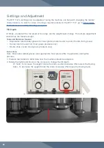
Page 22: ...rials Needed Disposable latex rubber gloves for food grade products and to protect hands from grease Hairnet and or beard net food grade products only Sterile shoe covers food grade products only Instructions Note Wear latex rubber gloves and appropriate food grade attire if applicable during this process 1 Produce test tablets to determine how the machine should be adjusted 2 Rotate the right han...

Page 23: ...rade products only Sterile shoe covers food grade products only Instructions Note Wear latex rubber gloves and appropriate food grade attire if applicable during this process 1 Adjust both of the Hopper nuts and screw bolts by hand and raise lower the Hopper to the desired position inside the Fill Tray s gate 1 1 Note The lower and closer the Hopper is to the Die table the less flow there will be ...

Page 24: ...et and or beard net food grade products only Sterile shoe covers food grade products only Instructions Note Wear latex rubber gloves and appropriate food grade attire if applicable during this process 1 Lift up the Hopper and loosen the Perspex Casing s top four screws and remove it 2 Loosen the Fill Tray Thumb Bolts by hand and remove them 3 Loosen the Fill Tray Scrapers with a crosshead screwdri...

Page 25: ...l Tray Height Adjusters accordingly and tighten their bolts 6 Resecure the Fill Tray Scrapers with a crosshead screwdriver 7 Tighten the Fill Tray Thumb Bolts by hand 8 Resecure the Perspex Casing and reinsert the Hopper ...

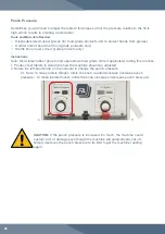
Page 26: ...er gloves and appropriate food grade attire if applicable during this process 1 Produce test tablets to determine how the machine should be adjusted 2 Rotate the left hand knob on the console to change the punch pressure 2 1 Note To make tablets thinner rotate the knob counterclockwise increase punch pressure To make tablets thicker rotate the knob clockwise decrease punch pressure CAUTION If the ...

Page 27: ... products only Instructions Note Wear latex rubber gloves and appropriate food grade attire if applicable during this process 1 Lift up the Hopper and loosen the Perspex Casing s top four screws and remove it 2 Loosen the Upper Pressure Cam Pressure Adjuster s bolt with an Allen key 3 Move the Upper Pressure Cam Housing Adjuster to increase or decrease the Upper Punch s penetration 3 1 Note To inc...

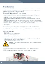
Page 28: ...ng in an air tight container and cover in lubricant Lubrication Regularly greasing your machine is vital to prolonging its operational life Parts that are not greased properly can make the machine seize up and cause major problems later LFA recommends maintaining a lubrication schedule for your RTP 118 which can be found in this section Tools and Materials Needed Grease gun RTP 118 Toolkit comes w...

Page 29: ...ease refer to the Tooling removal instructions on page 35 3 Lubricate the heads of the Upper Punches and Lower Punches with NLGI Grade 1 grease 4 Lubricate the barrels of the Upper Punches and Lower Punches with SAE 10 oil 5 Lubricate the Upper Tracking with NLGI Grade 1 grease 3 4 ...

Page 30: ...oor 7 Lubricate the Lower Pressure Cam Shaft s grease nipple with NLGI Grade 2 grease 8 Lubricate the Pressure Adjustment Gear with NLGI Grade 2 grease 9 Lubricate the Upper Pressure Cam Shaft s grease nipple with NLGI Grade 2 grease 7 8 ...

Page 31: ...31 10 Open the right hand side panel door 11 Lubricate the Fill Adjustment Gear s grease nipple with NLGI Grade 2 grease ...

Page 32: ...ive Shaft s bore and the Ejection Cam Fill Cam and Dosing Cam Inspect after every 3 months or 100 000 tablets and apply if dry If old gritty grease is present clean before lubricating NLGI Grade 2 Grease Nipple on Lower Pressure Cam Shaft On left side of RTP 118 open panel door Apply after every 100 000 tablets NLGI Grade 2 Grease Nipple on Upper Pressure Cam Shaft On the back of the Upper Pressur...

Page 33: ... of Upper Punches and Lower Punches Inspect and apply when dry NLGI Grade 1 Tooling Air tight container Cover and store in oil after cleaning Mineral oil Tooling Barrels The main shaft of the Upper Punches and Lower Punches Lubricate every time Tooling is installed in the press SAE 10 Gearbox On the Gearbox Inspect after every 3 months 460 Grade Worm Gear Oil Part Location Image Frequency Type of ...

Page 34: ...cess LFA s warranty policy go to https www lfatabletpresses com warranty If your part is eligible for warranty have your part s serial number on hand and please contact LFA UK Phone 44 0 0345 165 20 25 Email sales lfamachines com Taiwan Phone 886 2773 74704 Email sales asia lfamachines com USA Phone 682 312 0309 Email sales usa lfamachines com WARNING To prevent any potential personal injury ALWAY...

Page 35: ... tablet s ejection point can get lower until they are not ejecting correctly from the Die bores The three main causes of this are 1 tight Lower Punches due to buildup of excess fines in powder 2 high ejection forces that are caused by sticky powders clinging to the Die bore s wall and 3 powder that mixes with oil grease which creates a sandpaper effect on the Ejection Cam Fill Cam The Fill Cam pul...

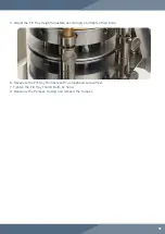
Page 36: ...with ball ends Tooling Upper Punches Dies and Lower Punches RTP 118 Toolkit comes with machine Lubricant NSF approved for food grade products Disposable latex rubber gloves for food grade products and to protect hands from grease Hairnet and or beard net food grade products only Sterile shoe covers food grade products only Remove the Old Tooling 1 Lift up the Hopper and loosen the Perspex Casing s...

Page 37: ...37 2 Loosen the Fill Tray s Thumb Bolts and remove them by hand 3 Remove the Fill Tray from the Turret 4 Remove the right hand panel door 5 Insert the Handle onto the Drive Belt Pulley socket ...

Page 38: ...38 6 Pull the Upper Punch upwards to remove it from the Turret ...

Page 39: ...al Plate with an Allen key 10 Rotate the Handle until a Lower Punch is aligned with where the Lower Punch and Die Removal Plate was previously 11 Gently pull on the Lower Punch s head through the hole 11 1 Note Be sure to have a firm hold on the Lower Punch so that it does not fall and become damaged 12 Repeat steps 10 11 until all Lower Punches are removed ...

Page 40: ...unch and Die Removal Plate was previously 14 Remove Die s set screw with an Allen key 15 Hold the Die Removal Bar up through the hole from which the Lower Punches were removed and into the Turret 16 Tap the Die from underneath the Die Plate until it pops up and remove it ...

Page 41: ...0 1 Note Make sure that the new Die is flush with the Turret 21 Reinsert the Die s set screw in the Turret and tighten with an Allen key 21 1 Note The Die s set screw are to be tensioned at 16 lbs ft 22 Rotate the Handle until the next new Die can be inserted 23 Repeat steps 18 22 until all the new Dies are secured in the Turret Note To help ensure that the Dies are inserted correctly LFA recommen...

Page 42: ...ch s head on the Lower Tracking 26 Rotate the Handle until the next new Lower Punch can be inserted 27 Repeat steps 24 26 until all the new Lower Punches are inserted into the Turret 28 Reinsert the Lower Punch and Die Removal Plate and secure it with an Allen key 28 1 Note Manually turn the RTP 118 Turret for a couple of rotations to ensure that the new Lower Punches are situated correctly ...

Page 43: ... 1 Note Be sure that the new Upper Punch s head is above the Upper Tracking to prevent damage 31 Rotate the Handle until the next new Upper Punch can be inserted 32 Repeat steps 29 30 until all the new Upper Punches are inserted into the Turret 32 1 Note Manually turn the RTP 118 Turret for a couple of rotations to ensure that the new Upper Punches are situated correctly ...

Page 44: ...e the Fill Tray back on the Turret 34 1 Note Please refer to the Fill Tray Height adjustment instructions on page 24 for calibration 35 Tighten the Fill Tray Thumb Bolts back onto the Fill Tray and RTP 118 by hand 36 Resecure the Perspex Casing and the Hopper ...

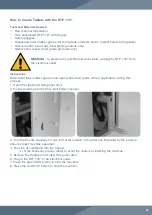
Page 45: ...keys with ball ends Crosshead screwdriver New Fill Tray part Disposable latex rubber gloves for food grade products and to protect hands from grease Hairnet and or beard net food grade products only Sterile shoe covers food grade products only WARNING To prevent any potential personal injury ALWAYS unplug the RTP 118 from the electrical outlet when replacing parts Instructions Note Wear latex rubb...

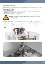
Page 46: ...46 2 Loosen the Fill Tray s thumb bolts by hand and remove them 3 Remove the Fill Tray Scrapers from the Fill Tray with a crosshead screwdriver 4 Take off the Fill Tray from the Turret ...

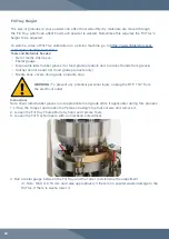
Page 47: ...age 24 for calibration 8 Tighten the Fill Tray Scrapers with a crosshead screwdriver 8 1 Note It is important to make sure that the Fill Tray Scraper blade furthest from the Ejection Chute is firmly up against the Die Table of the Turret To do this push down on the top of the blade while tightening the screws that hold it in place The Fill Tray Scraper blade closest to the Ejection Chute needs to ...

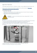
Page 48: ...per Tracking part Disposable latex rubber gloves for food grade products and to protect hands from grease Hairnet and or beard net food grade products only Sterile shoe covers food grade products only Instructions Note Wear latex rubber gloves and appropriate food grade attire if applicable during this process WARNING To prevent any potential personal injury ALWAYS unplug the RTP 118 from the elec...

Page 49: ...49 2 Loosen the Fill Tray s Thumb Bolts and remove them by hand 3 Remove the Fill Tray from the Turret 4 Remove the right hand panel door and insert the Handle onto the Drive Belt Pulley socket ...

Page 50: ...50 5 Pull the Upper Punch upwards to remove it from the Turret 6 Rotate the Handle until the next Upper Punch can be removed 7 Repeat steps 5 6 until all Upper Punches are removed ...

Page 51: ...am Housing 12 1 Note Use tools such as a flathead screwdriver and mallet to make its removal easier if needed 13 Remove each of the four Perspex Support Columns by turning them with a 450 mm adjustable wrench 8 Remove the four large nuts on the Perspex Support Columns with a socket wrench 9 Loosen the four set screws on top of the Upper Pressure Cam Housing with an Allen key ...

Page 52: ...nuts on the Perspex Support Columns with a socket wrench 20 Reinsert the bearings and the bearings cap on top of the Upper Pressure Cam Housing 21 Tighten the four set screws on top of the Upper Pressure Cam Housing with an Allen key 22 Insert an Upper Punch through the top of the Turret 23 Place the Upper Punch s head on the new Upper Tracking 23 1 Note Be sure that the Upper Punch s head is abov...

Page 53: ...e the Fill Tray back on the Turret 27 1 Note Please refer to the Fill Tray Height adjustment instructions on page 24 for calibration 28 Tighten the Fill Tray Thumb Bolts back onto the Fill Tray and RTP 118 by hand 29 Resecure the Perspex Casing and the Hopper ...

Page 54: ...s and Materials Needed Set of metric Allen keys with ball ends 36 mm socket wrench New Upper Pressure Cam part Disposable latex rubber gloves for food grade products and to protect hands from grease Hairnet and or beard net food grade products only Sterile shoe covers food grade products only Instructions Note Wear latex rubber gloves and appropriate food grade attire if applicable during this pro...

Page 55: ...ve the Upper Pressure Cam Pressure Adjuster with an Allen key 3 Pull out the Upper Pressure Adjuster from the Upper Pressure Cam Housing 4 Remove the Upper Pressure Cam Shaft from the Upper Pressure Cam Housing ...

Page 56: ...essure Cam Upper Pressure Cam Pressure Adjuster and the top of the Upper Pressure Cam Housing 7 1 Note Ensure that the Upper Pressure Cam Shaft s keyed section is in the correct position 8 Secure the Upper Pressure Cam Pressure Adjuster with an Allen key 9 Resecure the Perspex Casing and the Hopper 5 Remove the Upper Pressure Cam from the Upper Pressure Cam Housing ...

Page 57: ...ounterclockwise The V Belts are loose Replace the V Belts Parts may be loose Check the machine s parts and tighten as necessary The Gearbox needs oil Check the Gearbox s oil level and lubricate if necessary Heavy resistance during production The high friction areas are either unclean locked worn out or not greased properly Apply grease to the Grease Nipple points and all high friction areas and or...

Page 58: ...ere are flowing issues with the mix If the machine is able to make tablets with LFA s Firmapress then the problem is your mix Adjust your formulation If still an issue contact LFA for support Powder sticks to the Upper Punch There is damage to the Tooling or the Tooling s design is causing sticking Remove and replace the Tooling all Upper Punches Lower Punches and Dies There are issues with the mi...

Page 59: ...rs accordingly There is excess pressure Please read our article on Capping at https www lfatabletpresses com articles tablet capping Inconsistent tablet weight There are flowing issues with the mix If the machine is able to make tablets with LFA s Firmapress then the problem is your mix Adjust your formulation If still an issue contact LFA for support Soft tablets There is too little punch pressur...

Page 60: ... grease Hairnet and or beard net food grade products only Sterile shoe covers food grade products only Instructions Note Wear latex rubber gloves and appropriate food grade attire if applicable during this process Method 1 Lower the Punch Pressure 1 Remove all the excess powder 2 Rotate the left hand knob on the console clockwise to its limit 3 Rotate the right hand knob on the console clockwise t...

Page 61: ...ing abrasive Clean cloths Potable water Hairnet and or beard net food grade products only Sterile shoe covers food grade products only Instructions Note Wear latex rubber gloves and appropriate food grade attire if applicable during this process Remove Parts 1 Remove the Hopper the Perspex Casing the Fill Tray and the Tooling 1 1 Note Please refer to the replace Tooling and Fill Tray instructions ...

Page 62: ...ith a clean cloth 10 Lubricate part 11 Repeat steps 6 10 for each remaining part until they are all clean Clean the Turret and the Base 12 Remove any sticky materials from the Turret and Die Seat with the brushes that come in the RTP 118 Toolkit 13 Spray the RTP 118 base with the cleaner particularly in the Turret and the Tooling s location 14 Rinse the cleaner off with potable water and dry with ...

Page 63: ...ne Remove from machine Motor Clean in machine Clean in machine Clean in machine Clean in machine Clean in machine Remove from machine Clean in machine Clean in machine Gearbox Clean in machine Clean in machine Clean in machine Clean in machine Clean in machine Remove from machine Clean in machine Clean in machine Drive Belt Pulleys Clean in machine Clean in machine Clean in machine Clean in machin...

Page 64: ...ine has a high chance of contact with the food or drug product Disposable latex rubber gloves for food grade products and to protect hands from lubricant Hairnet and or beard net food grade products only Sterile shoe covers food grade products only Lubricating the Tooling If you are not using the machine for more than a week store the Tooling in an airtight container like the one pictured below an...

Page 65: ... the Hopper and loosen the Perspex Casing s bolts and remove it 3 Lubricate the Lower Cam Roller Shaft s grease nipple with a grease gun 4 Lubricate the Upper Pressure Cam Shaft s grease nipple with a grease gun 5 Rub grease on the Pressure Adjustment Gear 6 Lubricate the Fill Adjustment Gear with a grease gun ...

Page 66: ...gside the API that acts as a binding agent in the tablet powder Fill depth The amount of space that the powder can flow into in the Die Formulation Powder mix of the excipient and the API that is compressed to make tablets Granular material See Formulation Kilonewton kN The force to accelerate a mass of 1 kg at a constant 1 m per second The RTP range s pressure is measured in this unit Punches The...

Page 67: ... DQB0002 The Fill Tray Height Adjusters move the Fill Tray s position in proximity to the Turret which affects powder flow Lower Punch and Die Removal Plate DQC0027 The Lower Punch and Die Removal Plate can be removed to take out insert the Lower Punches and Dies from into the Turret Description of RTP 118 Parts Fill Tray Scrapers DQC0007 The Fill Tray Scrapers 2 help keep the powder flowing into ...

Page 68: ... and is used to manually operate the RTP 118 Pressure Sensor Dial DQC0046 and Housing DQC0031 Whenever the Pressure Knob is turned the Pressure Sensor Dial and Housing moves the Lower Pressure Cam to increase or decrease pressure Adjustment Knob Linkages DQC0042 The Adjustment Knob Linkages fit into the Fill Depth Adjustment and Pressure Sensor Dial which are then turned by the Fill Depth Knob and...

Page 69: ...ay DQC0006 The Fill Tray helps channel the dry materials into the Dies bores and also pushes the tablets out of the way and into the Ejection Chute Hopper DQC0040 The Hopper contains the powder and allows it to flow onto the Fill Tray and into the Dies bores Upper Tracking DQC0013 The Upper Tracking holds the Upper Punches and guides their movement through the Turret ...

Page 70: ...Cam Housing Upper Pressure Cam Housing DQC022 The Upper Pressure Cam Housing contains the Upper Pressure Cam and the Perspex Support Columns Perspex Casing DQC0039 The Perspex Casing covers the upper section of the RTP 118 to prevent cross contamination and personal injury Handles not included Perspex Casing Handle DQC0053 The Perspex Casing Handle is used to help remove the Perspex Casing ...

Page 71: ...ifications Tooling Specification Euro B Number of dies 9 Production capacity 32 400 hr Max diameter of tablet 16 mm round 19 mm irregular Max fill depth 17 mm Thickness of tablet 8 mm Max pressure 60 kN Number of filling stations 1 Double layered tablet No Kilowatts 3 7 kW Volts 240 V or 220 V Hertz 60 or 50 Amps 14 6 or 14 0 Overall size 1200 mm x 670 mm x 675 mm Weight 330 kg approximately 728 l...

Page 72: ...dup of powder in front of the Fill Tray If occurring either a make mix more granular b check the Fill Tray for damage c clear the buildup or d adjust the Fill Tray and or Hopper Occasionally check the Motor s temperature If it starts to overheat turn off the machine let it cool down and grease it to ensure smooth operation Ensure that the Hopper does not run out of powder Weigh five or ten sample ...

Page 73: ...73 Diagrams RTP 118 Euro B Tooling Dimensions _ _ Drawing Name Product Name Version Provided By Euro B Tooling Dimensions Euro B tooling V1 0 Darrell Wagoner ...

Page 74: ...74 RTP 118 Dimensions Drawing Name Product Name Version Provided By RTP 118 Dimensions RTP 118 V1 0 Callie Scott www lfamachines com 41 00 588 450 97 97 1075 53 189 450 ...

Page 75: ...75 RTP 118 Exploding Diagram www lfamachines com Drawing Name Product Name Version Provided By RTP 9 Explosive Diagram RTP 9 V1 0 LFA Machines ...

Page 76: ...1 RY01 PBL02 LS02 LS03 PX01 MA MC PBL01 G E E 1001 1002 1003 1004 1005 1006 1007 1008 1009 1010 1011 1013 1012 1019 1018 1017 1014 1015 1016 S04 R04 S03 R03 S02 R02 1025 1 3 E TL N5MY2 E E MS2 137 RY01 POWER SOURCE 1 220V 60Hz RS02 RS01 PL01 G Drawing Name Product Name Version Provided By 1 0 LFA Machines www lfamachines com RTP 118 RTP 118 Wiring Diagram ...

Page 77: ...ularly upload videos to give you a visual aid that will hopefully support you in your tablet production efforts To watch our videos visit https www youtube com channel UCwtbcwja77ai7vX2o34FUkQ LFA Machines Social Media Social media is a great way to keep yourself updated on new developments and exciting things happening at LFA Machines The list below contains our current social media pages Twitter...

Page 78: ...xfordshire United Kingdom 6601 Will Rogers Blvd Fort Worth Texas United States Business Parc Am Trippelsberg 92 Düsseldorf Germany 7F 5 No 2 Sec 2 Taiwan Blvd West Dist Taichung City 403 Taiwan United Kingdom United States Germany Taiwan Copyright 2021 by LFA Machines ...

Reviews: