


GA01201_1002 - 07/2005
9
Description
1.1
Function
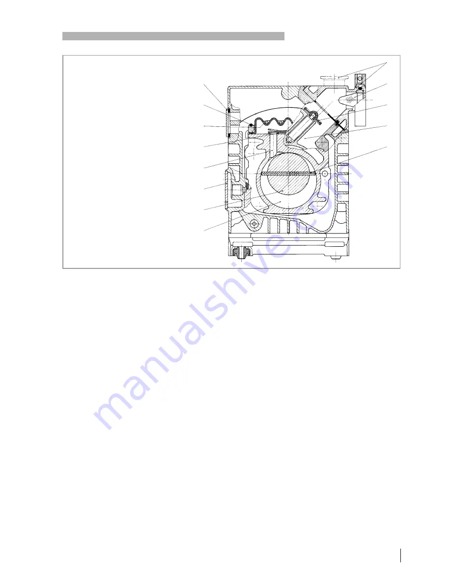
The rotor (2/7), mounted eccentrically in the pump chamber (2/6), has two
radially sliding vanes (2/5) which divide the pump chamber into several
compartments. The volume of each compartment changes periodically
with the rotation of the rotor.
As a result, gas is sucked in at the intake port (2/1). The gas passes
through the inlet screen (2/2), flows past the open anti-suckback valve (2/3)
and then enters the pump chamber (2/6). In the pump chamber, the gas is
passed on and compressed, after the inlet aperture is closed by the vane.
The oil injected into the pump chamber is used for sealing and lubricating.
The slap noise of the oil in the pump which usually occurs when attaining
the ultimate pressure is prevented by admitting a very small amount of air
into the pump chamber.
The compressed gas in the pump chamber is ejected through the exhaust
valve (2/10). The oil entrained in the gas is coarsely trapped in the internal
demister (2/11); there the oil is also freed of mechanical impurities. The gas
leaves the TRIVAC B through the exhaust port.
During compression, a controlled amount of air - the so-called gas ballast
- can be allowed to enter the pump chamber by opening the gas ballast
valve (position I). The gas ballast stops condensation of vapours in the
pump chamber up to the limit of water vapour tolerance as specified in the
technical data for the pump.
Fig. 2 Sectional drawing of the TRIVAC B
Key to Fig. 2
1
Intake port
2
Inlet screen
3
Anti-suckback valve
4
Intake channel
5
Vane
6
Pump chamber
7
Rotor
8
Cover plate, connection for inert gas ballast
9
Exhaust channel
10 Exhaust valve
11 Internal demister
12 Spring buckles
13 Cover plate, connection for oil filter
Operating Principle
Operating with gas ballast
Oil filter
1
2
3
4
5
6
7
8
9
10
11
12
13