•
Make sure that the paper size and type are set correctly on the Embedded Web Server or the computer.
Note:
Depending on your operating system, access the Paper menu using Local Printer Settings Utility or
Printer Settings.
•
Store paper according to manufacturer recommendations.
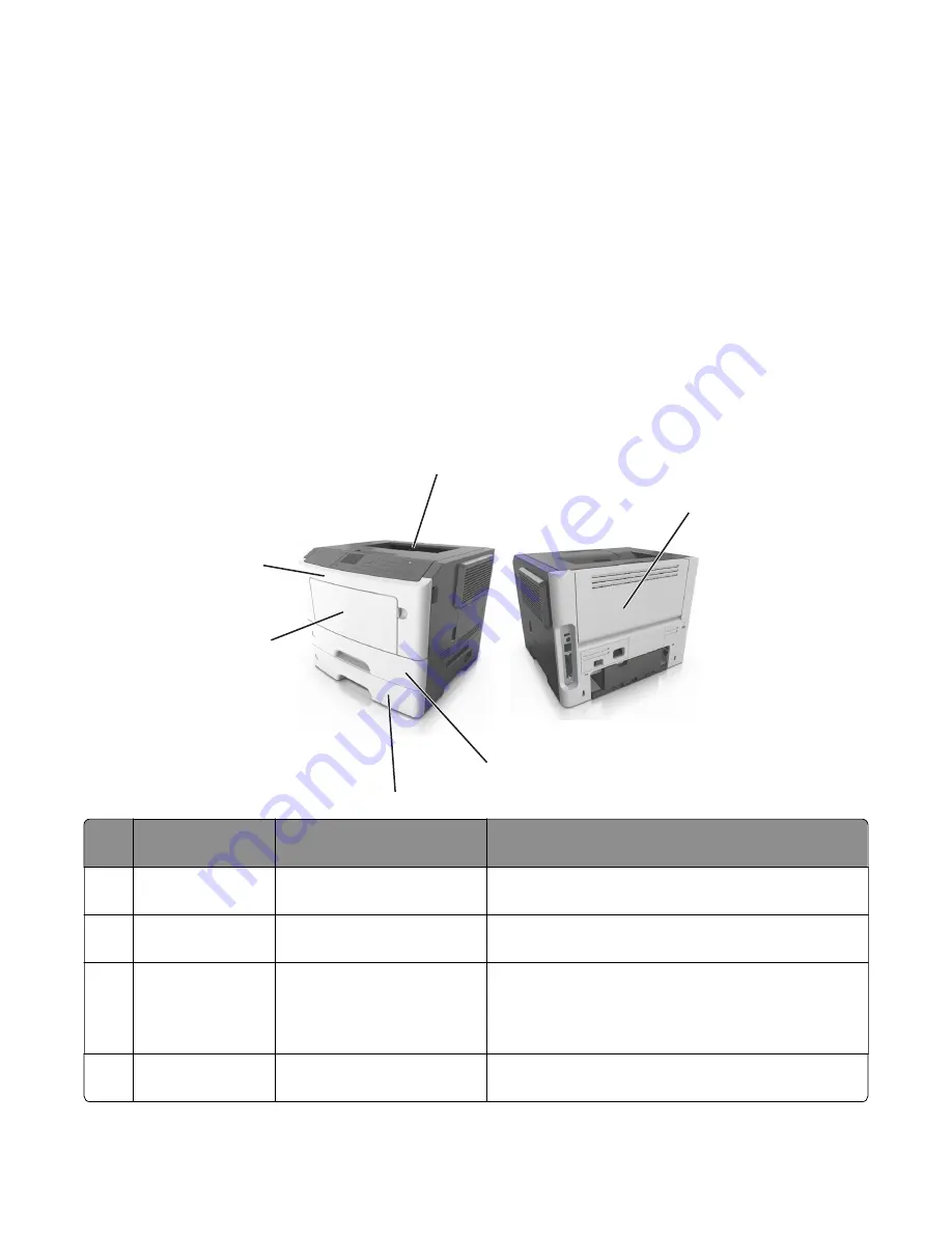
Understanding jam messages and locations
When a jam occurs, a message indicating the jam location and information to clear the jam appears on the
printer display. Open the doors, covers, and trays indicated on the display to remove the jam.
Notes:
•
When Jam Assist is set to On, the printer automatically flushes blank pages or pages with partial prints to
the standard bin after a jammed page has been cleared. Check your printed output stack for discarded
pages.
•
When Jam Recovery is set to On or Auto, the printer reprints jammed pages. However, the Auto setting
does not guarantee that the page will print.
1
5
6
2
3
4
#
Area
Printer control panel
message
What to do
1
Standard bin
[x]
‑
page jam, clear standard
bin. [20y.xx]
Remove the jammed paper.
2
Rear door
[x]
‑
page jam, open rear door.
[20y.xx]
Open the rear door, and then remove the jammed
paper.
3
Tray 1
[x]
‑
page jam, remove tray 1 to
clear duplex. [23y.xx]
Pull tray 1 completely out, then push the front duplex
flap down, and then remove the jammed paper.
Note:
You may need to open the rear door to clear
some 23y.xx paper jams.
4
Tray [x]
[x]
‑
page jam, remove tray [x].
[24y.xx]
Pull the indicated tray out, and then remove the jammed
paper.
4514-6xx
Diagnostics and troubleshooting
80
Summary of Contents for M3150
Page 12: ...Part name index 393 4514 6xx Table of contents 12 ...
Page 20: ...4514 6xx 20 ...
Page 38: ...4514 6xx 38 ...
Page 172: ...4514 6xx 172 ...
Page 246: ...3 Remove two screws A and then remove the cooling fan mount A 4514 6xx Parts removal 246 ...
Page 256: ...5 Remove the four screws B and then remove the right front mount B 4514 6xx Parts removal 256 ...
Page 260: ...b Set the spring over the plunger 4514 6xx Parts removal 260 ...
Page 277: ...3 Squeeze the latches B to release the left and right links B 4514 6xx Parts removal 277 ...
Page 300: ...3 Place the printer on its rear side 4 Release the sensor flag A 4514 6xx Parts removal 300 ...
Page 301: ...5 Remove the screw B 6 Remove the sensor flag bracket C 4514 6xx Parts removal 301 ...
Page 323: ...3 Swing the right cover backward to remove 4 Remove the screw D 4514 6xx Parts removal 323 ...
Page 333: ...4514 6xx 333 ...
Page 335: ...Assembly 1 Covers 4514 6xx Parts catalog 335 ...
Page 338: ...4514 6xx Parts catalog 338 ...
Page 339: ...Assembly 2 Electronics 1 1 2 3 4 5 7 9 10 11 6 8 12 4514 6xx Parts catalog 339 ...
Page 342: ...4514 6xx Parts catalog 342 ...
Page 343: ...Assembly 3 Electronics 2 4 3 2 1 5 6 8 9 7 4514 6xx Parts catalog 343 ...
Page 345: ...4514 6xx Parts catalog 345 ...
Page 346: ...Assembly 4 Frame 10 11 12 13 14 9 1 5 6 7 8 4 4 2 3 4514 6xx Parts catalog 346 ...
Page 349: ...Assembly 5 Option trays 3 4 5 6 1 2 4514 6xx Parts catalog 349 ...
Page 354: ...4514 6xx Parts catalog 354 ...
Page 356: ...4514 6xx Parts catalog 356 ...
Page 364: ...4514 6xx 364 ...
Page 376: ...4514 6xx 376 ...
Page 386: ...4514 6xx Index 386 ...
Page 392: ...4514 6xx Part number index 392 ...
Page 398: ...4514 6xx Part name index 398 ...


