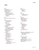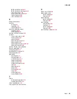
Index
I-3
4036-402
MFD controller card
3-41
MFD controller card cage
3-38
paper input tray
3-18
power distribution card
3-41
upper housing
3-32
user interface
3-30
S
safety information
v
scanner
moving
5-3
operation
1-5
specifications
1-3
scanner calibration sheet
adjustment
3-2
parts catalog
6-6
screws, CCD card screws
3-5
sensors
cover open sensor
3-28
home position
4-1
paper feed
6-3
paper length sensor
4-1
paper position
4-1
paper present sensor
3-27
,
4-1
paper size sensor
3-21
service checks, see symptoms
service guidelines
1-2
software update
3-4
specifications, scanner
1-3
start diagnostics
2-1
symptoms
boot failure
2-7
double feeds
2-9
erratic behavior
2-7
image missing
2-8
image unclear
2-8
irregular movement
2-8
jitter
2-8
paper jams
2-9
power
2-6
scanning
2-6
,
2-7
skew
2-9
sound (ADF)
2-9
sound (flatbed)
2-9
T
theory
mechanical operation
1-5
system description
1-4
tools, maintenance
1-2
touch panel see user interface
U
upper cover, ADF
3-8
upper guide, ADF
parts catalog
6-3
removal
3-9
upper housing
parts catalog
6-3
removal
3-32
user interface
lamp flashes
2-4
location
4-2
parts catalog
6-3
removal
3-30
user interface cables
4-2
,
6-5
Summary of Contents for 16C0365 - 5500 MFP
Page 49: ...Repair information 3 25 4036 402 3 Remove the pick pad ...
Page 55: ...Repair information 3 31 4036 402 5 Disconnect the cables 6 Remove the user interface ...
Page 68: ...3 44 Service Manual 4036 402 ...
Page 69: ...Connector locations 4 1 4036 402 4 Connector locations Locations Paper path and sensors ...
Page 70: ...4 2 Service Manual 4036 402 Internal view ...
Page 76: ...5 4 Service Manual 4036 402 ...
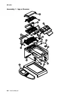
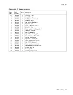
Page 78: ...6 2 Service Manual 4036 402 Assembly 1 Upper Scanner ...
Page 86: ...I 4 Service Manual 4036 402 ...

